
Laser leveling rod with an angle conversion mechanism
A technology of angle conversion and conversion mechanism, which is applied in the direction of measuring inclination, measuring devices, instruments, etc., and can solve problems such as the inability to find the angle of the measured object or draw an arbitrary angle line
- Summary
- Abstract
- Description
- Claims
- Application Information
AI Technical Summary
Problems solved by technology
Method used
Image

Examples
Embodiment Construction
[0013] The present invention will be further described through the embodiments below with reference to the accompanying drawings.
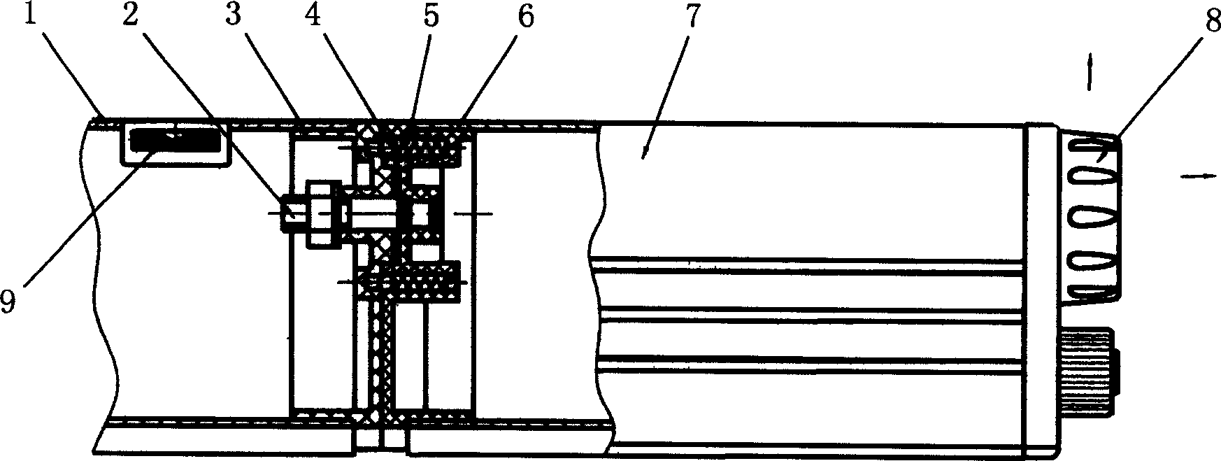
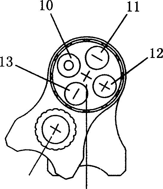
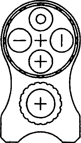
[0014] Refer to attached figure 1 to attach Figure 4 A laser level with an angle conversion mechanism includes a rear foot 1, a pin shaft 2, a connector 3, a positioning mechanism, a connector 2 6, a front ruler 7, a light splitting conversion mechanism 8, and a universal blister 9. Among them, the connector one 3 and the connector two 6 are connected together by the pin shaft 2, the connector one 3 is fixed on the rear foot 1, and the connector two 6 is fixed on the front ruler 7; the positioning mechanism consists of four pairs of steel balls 4 , spring 5, wherein the spring 5 is set in the spring hole of the connector two 6, one end of the spring 5 is against the steel ball 4, and the axis of the pin shaft 2 is set on the connector one 3 every 15 degrees with the center of the circle. The matching positioning hole of the steel ball 4 ensures...
PUM
 Abstract
Description
Claims
Application Information