Protective relay with synchronized phasor measurement capability for use in electric power systems

A technology for protecting relays and power systems, which is applied in the direction of using AC to DC for measurement, emergency protection circuit devices, and automatic disconnection emergency protection devices, which can solve problems such as incompatibility.

Inactive Publication Date: 2005-07-27
SCHWEITZER ENGINEERING LABORATORIES
View PDF0 Cites 12 Cited by
  • Summary
  • Abstract
  • Description
  • Claims
  • Application Information

AI Technical Summary

Problems solved by technology

Therefore, such systems are not suitable for those protection applications requiring synchronized phasor measurements

Method used


Image

  • Protective relay with synchronized phasor measurement capability for use in electric power systems
  • Protective relay with synchronized phasor measurement capability for use in electric power systems
  • Protective relay with synchronized phasor measurement capability for use in electric power systems

Examples


Embodiment Construction

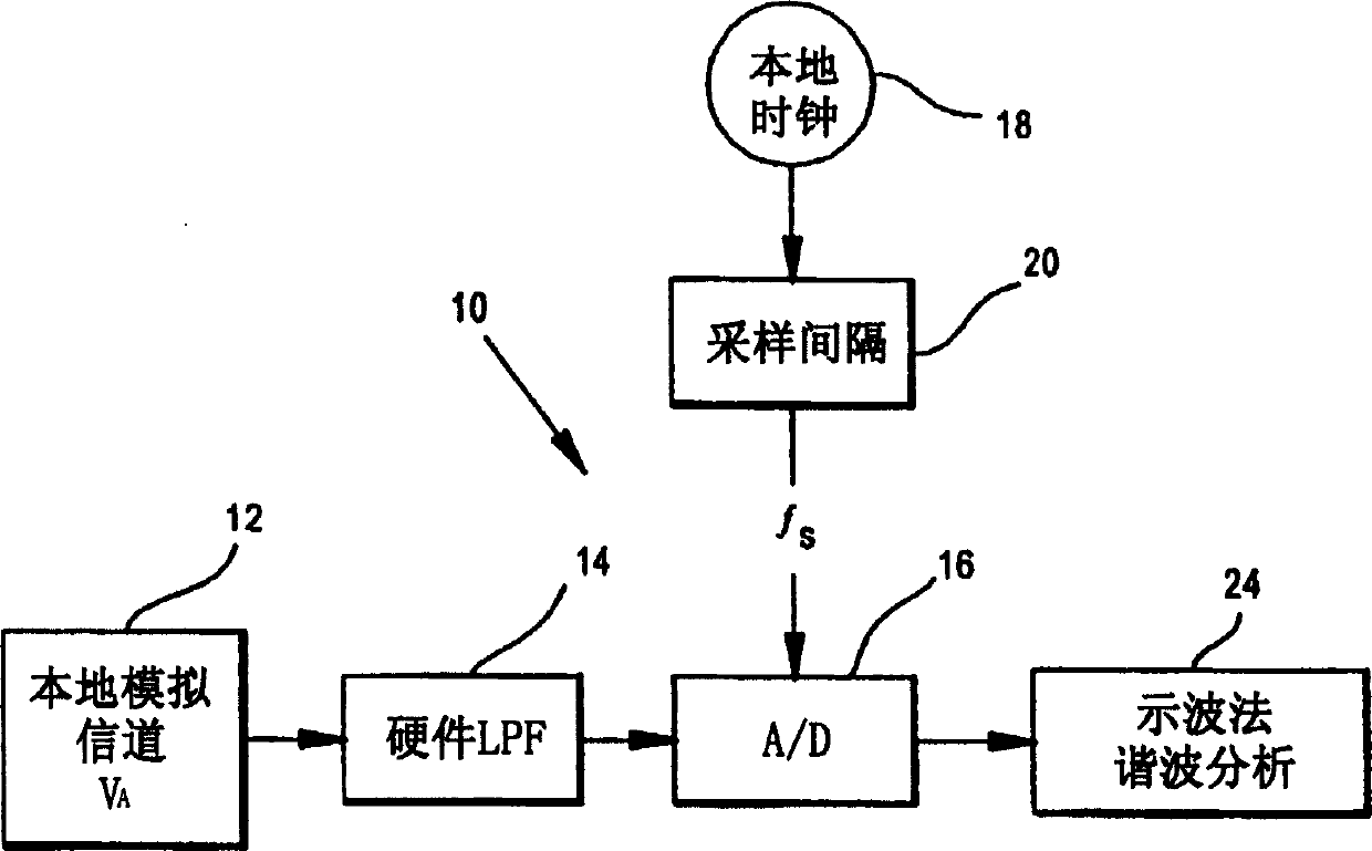
[0013] As mentioned above, some power system monitoring devices, such as digital fault recorders, require analog voltage and current values ​​from the power line at fixed time intervals to perform voltage and current oscillometric analysis and harmonic analysis on the entire power system. Such a system is shown by 10 in Figure 1, with a voltage source V A Use 12 to represent. Typically, the analog data includes all three voltage phases and all three current phases from the power line.

[0014] Analog signal V A (at the appropriate magnitude level, provided by the transformer) is led to a low pass filter 14 and then to an A-D converter 16 . This is the normal situation. Local clock source 18 in FIG. 1 operates at a particular selected sampling interval (block 20) ​​to sample A-D converter 16 at a selected rate, eg, 8000 samples per second. The resulting time-sampled signal is sent to a conventional processing system 24 for oscillometric and harmonic analysis. Since the tim...


PUM


Abstract

The relay system obtains voltage and current values from a power line and uses a first sampling element to sample the voltage and current values at selected intervals of time. The resulting sampled signals are used for power system-wide protection, control, monitoring and metering. The sampled signals are then resampled at a rate which is a selected multiple of the power system frequency. The results of the resampling are used by processing circuitry for protection functions including fault determinations.

Description

technical field [0001] The present invention relates generally to the monitoring and protection of electric power systems, and more particularly to power system relay devices capable of monitoring system-wide performance, such as utilizing voltage and current oscillometric methods and harmonic analysis and voltage / current synchronization Phasor measurements are also able to provide protection functions such as line distance protection for fault determination. Background technique [0002] To date, system-wide power monitoring functions, including system control as well as interference analysis and harmonic frequency analysis, for example, have required sampling data from power lines referenced to time, either a local clock or an absolute time reference such as from a Global Positioning System. For example, digital fault recorders require data (current and voltage values) from power lines at regular intervals for voltage and current oscillometric and harmonic analysis. Typic...

Claims


Application Information

Patent Timeline
Patent Type & Authority Applications(China)
IPC IPC(8): H02H1/00H02H3/40
CPCH02H1/0007H02H3/40
Inventor E·O·施魏策尔三世L·S·安德森A·古斯曼-卡西利亚斯G·C·茨威格勒G·本穆亚尔
Owner SCHWEITZER ENGINEERING LABORATORIES
Why Eureka
Try Eureka