Motor controlling circuit with controllable driven voltage supply

A technology of motor control and driving voltage, which is applied in the direction of control system, motor generator/starter, starter of a single DC motor, etc., and can solve problems such as excessive disturbance

Inactive Publication Date: 2005-10-12
GLOBAL MIXED MODE TECH
View PDF0 Cites 8 Cited by
  • Summary
  • Abstract
  • Description
  • Claims
  • Application Information

AI Technical Summary

Problems solved by technology

However, the PWM technique causes the supply voltage source V m and excessive disturbance of the drive voltage applied to the

Method used


Image

  • Motor controlling circuit with controllable driven voltage supply
  • Motor controlling circuit with controllable driven voltage supply
  • Motor controlling circuit with controllable driven voltage supply

Examples


Embodiment Construction

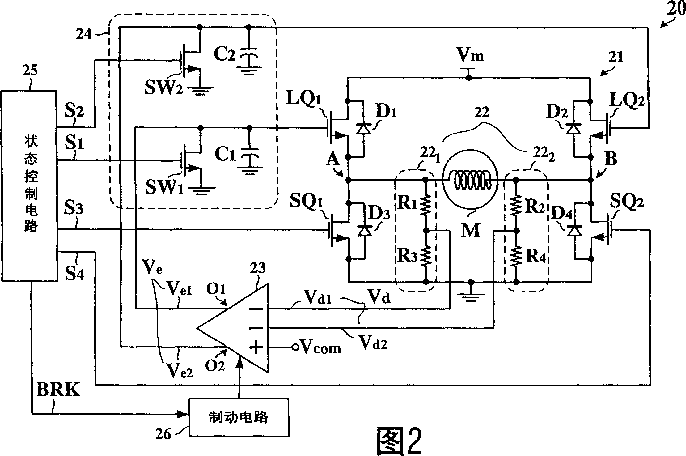
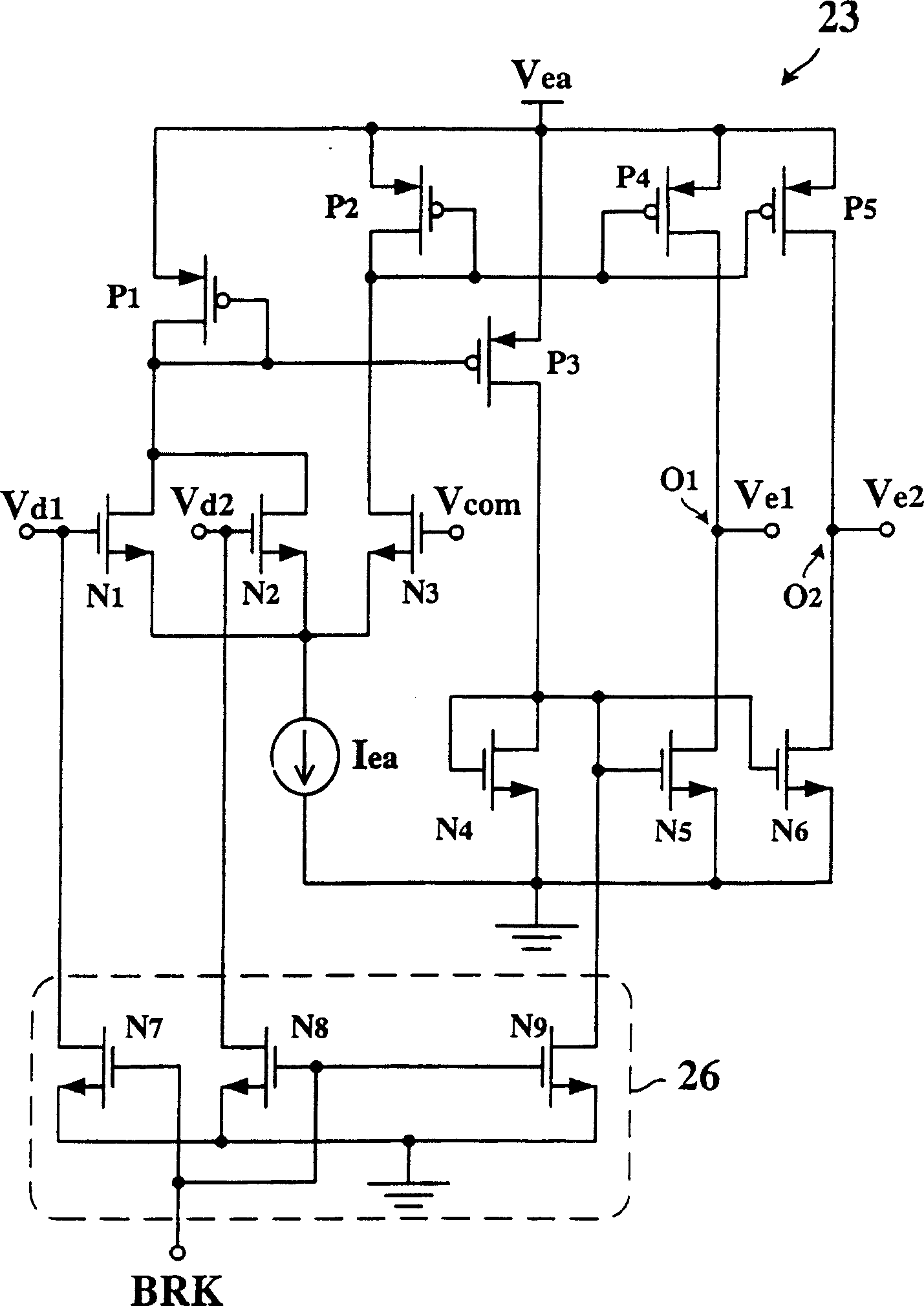
[0028] FIG. 2 shows a circuit diagram of an example of a motor control circuit 20 according to the present invention. Referring to FIG. 2 , the motor control circuit 20 includes an H-bridge circuit 21 , a voltage detection circuit 22 , an error amplifier 23 , a feedback circuit 24 , and a state control circuit 25 .

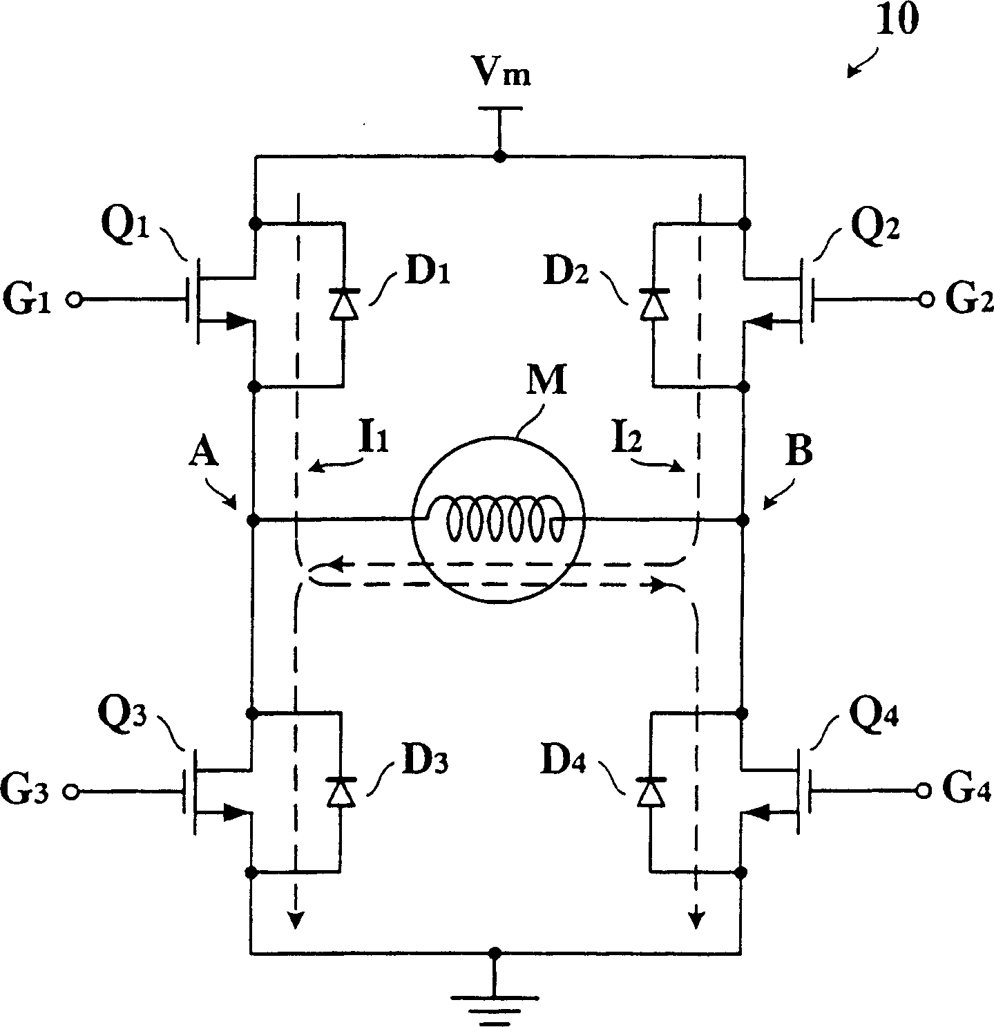
[0029] The H-bridge circuit 21 includes two linear units LQ 1 with LQ 2 and two switch units SQ 1 with SQ 2 . Linear unit LQ 1 with LQ 2 used to couple the supply voltage source V m with the motor M, while the switching unit SQ 1 with SQ 2 It is used to couple the motor M with the ground potential. Linear unit LQ 1 with LQ 2 The operating states include linear mode, conduction mode, and non-conduction mode, and the switch unit SQ 1 with SQ 2 The operating states include conduction mode and non-conduction mode. The term "linear mode" refers to an operating state in which the equivalent resistance value varies substantially linearly with the control si...


PUM


Abstract

The H-bridge circuit consists of first and second switch unit, and first and second linear unit, and is used to impress driving current on motor. The error amplifier generates error signal that presents the difference between command current signal and driving current detected by current detection circuit. The status control circuit simultaneously controls first and second switch unit and feed back circuit. The error signal is selectively impressed on first and second linear unit to make one of them operate at linear mode and other one operate at off state in order to control driving current being in direct proportion to command current signal. The status circuit also controls braking circuit to make error signal convert to braking signal, and first and second linear unit operate at on state mode.

Description

【Technical field】 [0001] The present invention relates to a motor control circuit, in particular to a control circuit that provides a controllable driving voltage to the motor. 【Background technique】 [0002] Generally speaking, an H-bridge circuit composed of four switching transistors can be applied to provide driving voltage to motors, such as DC motors, stepping motors, and voice coil motors, etc., so as to control the rotation direction, speed, and other operating characteristics. [0003] figure 1 A circuit diagram of a prior art H-bridge circuit 10 for driving a motor M is shown. refer to figure 1 , the motor M is coupled to the supply voltage source V via the H-bridge circuit 10 m and ground potential. Although the motor M is actually a complex system composed of many mechanical and electrical components, the driving voltage is basically applied to the coils in the motor M to generate a magnetic field. Therefore, the word "motor" in the following mainly refers ...

Claims


Application Information

Patent Timeline
IPC IPC(8): H02P1/22H02P7/00H02P7/291
Inventor 陈企扬陈立政
Owner GLOBAL MIXED MODE TECH
Why Eureka
Try Eureka