Motor controlling circuit with controllable driven voltage supply
A technology of motor control and driving voltage, which is applied in the direction of control system, motor generator/starter, starter of a single DC motor, etc., and can solve problems such as excessive disturbance
- Summary
- Abstract
- Description
- Claims
- Application Information
AI Technical Summary
Problems solved by technology
Method used
Image
Examples
Embodiment Construction
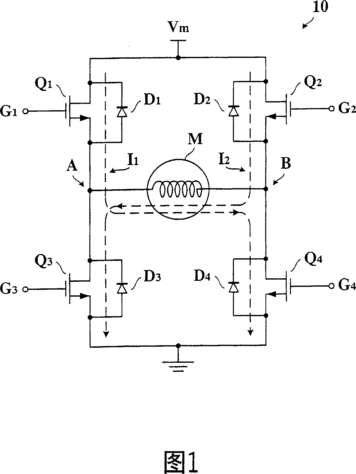
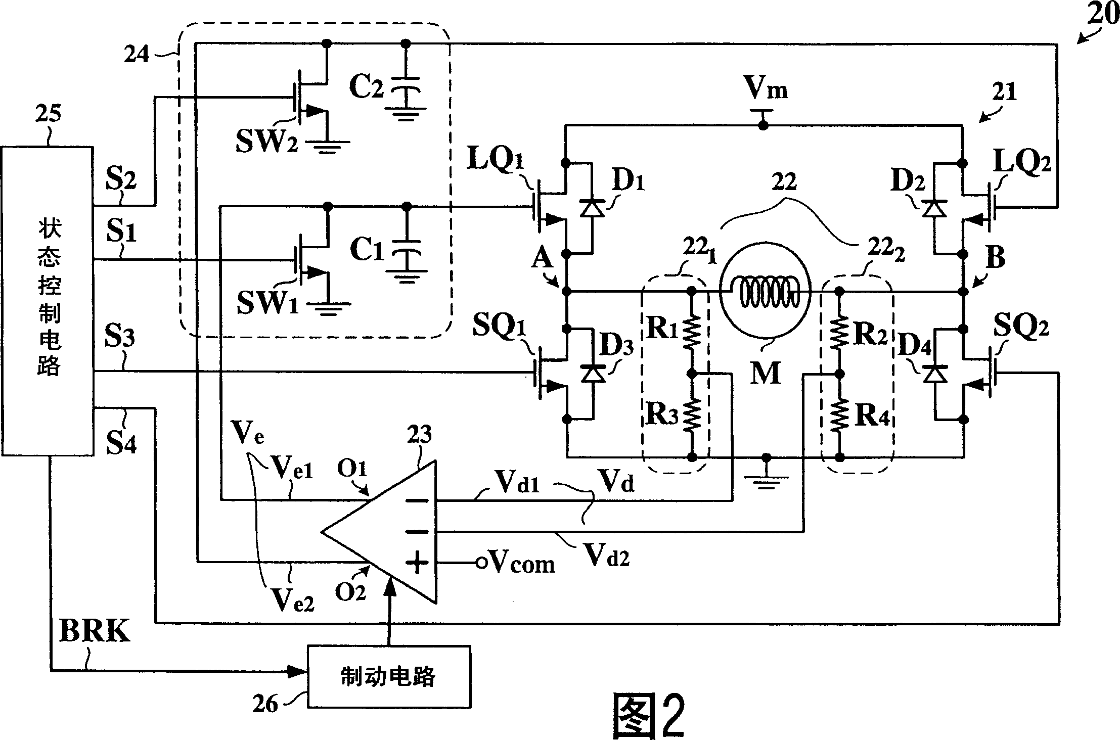
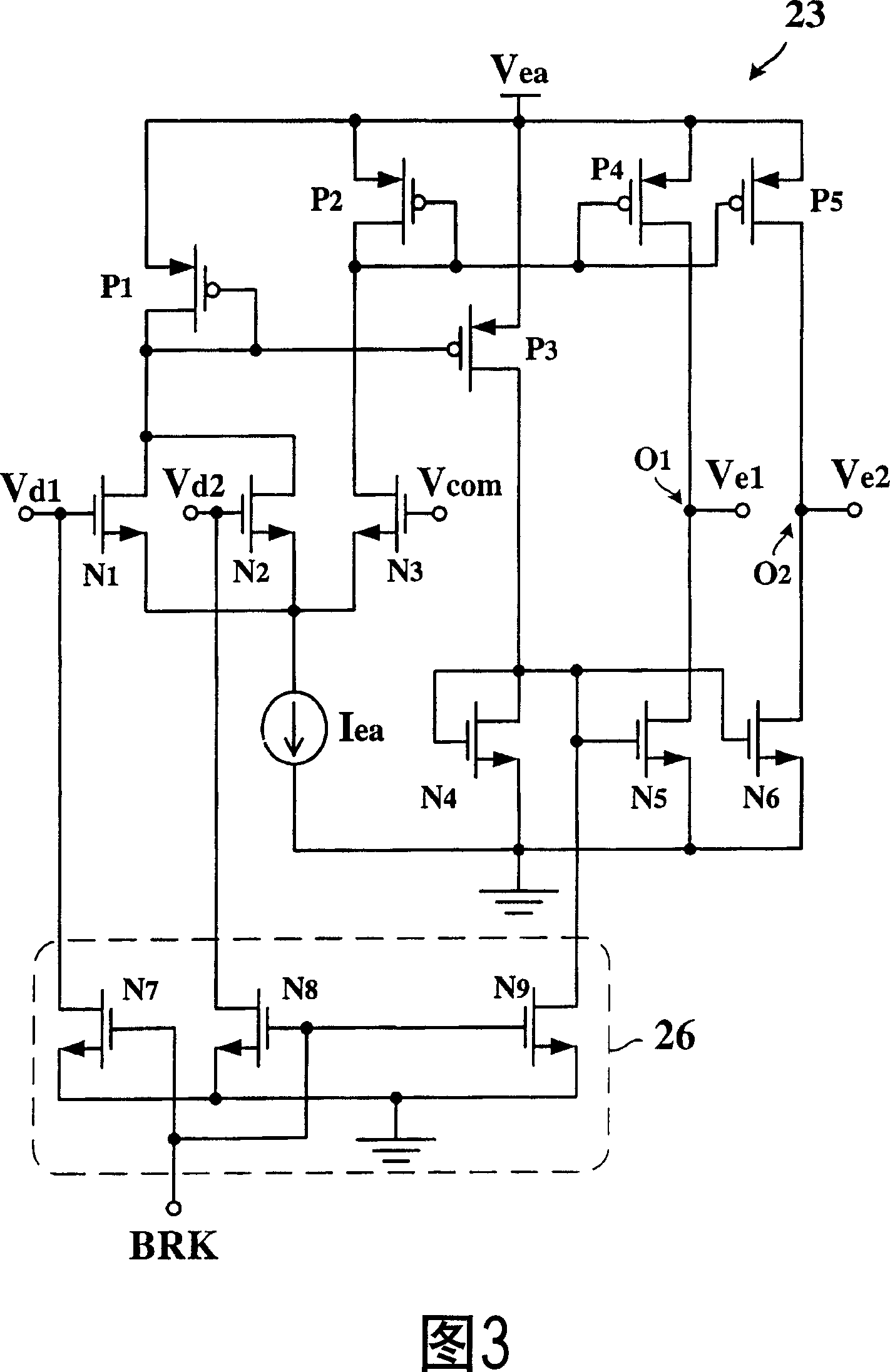
[0028] FIG. 2 shows a circuit diagram of an example of a motor control circuit 20 according to the present invention. Referring to FIG. 2 , the motor control circuit 20 includes an H-bridge circuit 21 , a voltage detection circuit 22 , an error amplifier 23 , a feedback circuit 24 , and a state control circuit 25 .
[0029] The H-bridge circuit 21 includes two linear units LQ 1 with LQ 2 and two switch units SQ 1 with SQ 2 . Linear unit LQ 1 with LQ 2 used to couple the supply voltage source V m with the motor M, while the switching unit SQ 1 with SQ 2 It is used to couple the motor M with the ground potential. Linear unit LQ 1 with LQ 2 The operating states include linear mode, conduction mode, and non-conduction mode, and the switch unit SQ 1 with SQ 2 The operating states include conduction mode and non-conduction mode. The term "linear mode" refers to an operating state in which the equivalent resistance value varies substantially linearly with the control si...
PUM
 Abstract
Description
Claims
Application Information
 - R&D
- Intellectual Property
- Life Sciences
- Materials
- Tech Scout
- Unparalleled Data Quality
- Higher Quality Content
- 60% Fewer Hallucinations
Browse by: Latest US Patents, China's latest patents, Technical Efficacy Thesaurus, Application Domain, Technology Topic, Popular Technical Reports.
© 2025 PatSnap. All rights reserved.Legal|Privacy policy|Modern Slavery Act Transparency Statement|Sitemap|About US| Contact US: help@patsnap.com


