Draining pump

A drainage pump and pump body technology, which is applied in the direction of pumps, pump devices, and prevention of condensed water. It can solve the problems of affecting the head and flow, low head, and complex structure of the drainage pump, so as to reduce the degree of turbulence and noise. generated effect

Active Publication Date: 2006-07-19
ZHEJIANG SANHUA CLIMATE & APPLIANCE CONTROLS GRP CO LTD
View PDF1 Cites 11 Cited by
  • Summary
  • Abstract
  • Description
  • Claims
  • Application Information

AI Technical Summary

Problems solved by technology

The structure of the drainage pump is complex, because the disc is installed, which limits the working capacity of the drainage pump, affecting the lift and flow improvement; and most of these drainage pumps work in non-design conditions, such as low water level and low lift, high water level and low The lift often causes the drainage pump to run idling with water, so that the mixture of water and air moves repeatedly in the drainage pipeline and cannot be discharged, resulting in additional noise

Method used


Image

  • Draining pump
  • Draining pump
  • Draining pump

Examples


Embodiment Construction

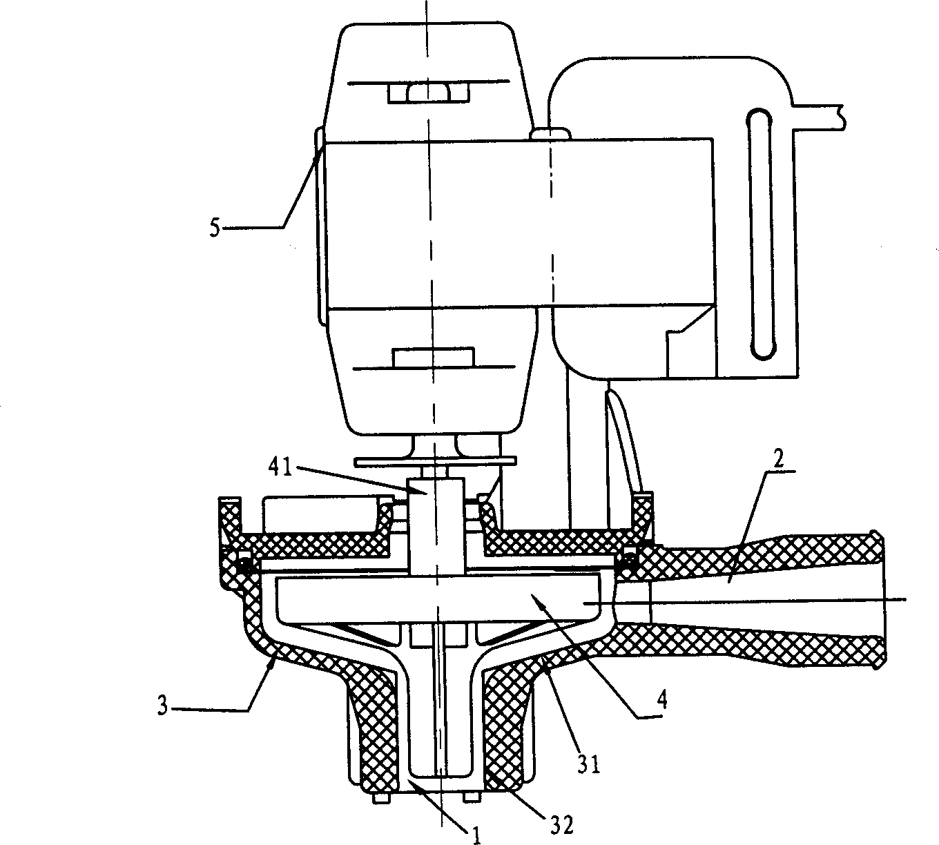
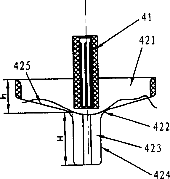
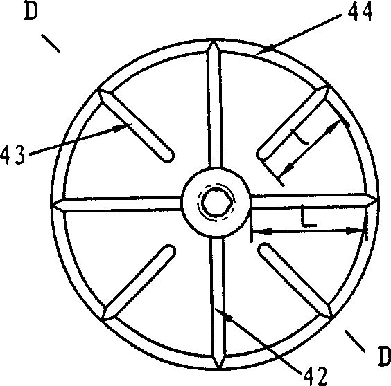
[0022] As shown in the figure, the drainage pump includes a pump body 3 with a water inlet 1 at the lower end and a water outlet 2 at the upper side, an impeller 4 placed in the pump body, and a motor 5 that rotates the impeller 4. The cylindrical shape of the pump body 3 The center of the water inlet 1 is concentric with the center of the output shaft of the motor 5 . The middle part of the impeller 4 has a shaft connection part 41 connected with the output shaft of the motor, and the upper part of the impeller 4 has four main blades 42 arranged radially with the shaft connection part 41 as the center. The adjacent main blades form a 90-degree angle. 42 is in the shape of "Γ" and consists of a flat working part 421 and a diversion part 423, which are connected together by a curved surface 422. The height h of the working part 421 is half of the height H of the diversion part 423. The distance between the outer edge 424 of the guide part and the opposite part 32 of the inner w...


PUM


Abstract

The invention relates to a discharge pump used in refrigeration system, which can overcome the defects of present discharge pumps which often depart from designed position, with lower efficiency and large noise. The invention comprises a pump which has an inlet at lower end and an outlet at upper part; a blade wheel inside the pump and a motor rotating the blade wheel. It is characterized in that: said blade wheels comprise main blades, short blades between nearby main blades, a stabilizing ring covering the upper edge of main blades and the outer edge of short blades, and an axial connection part connected with the output axle of motor. Wherein, the main and short blades are radial distributed with the center of the axes of axial connection part; the inner edge of main blade is connected to the axial connection part and the inner edge of short blade is distantly arranged from the axial connection part. The invention can improve the flux, the delivery lift, the flowing property and reduce the noise.

Description

technical field [0001] The present invention relates to a drain pump, in particular to a drain pump which is installed in a drain tank for storing condensed water of an air conditioner and discharges the condensed water to the outside. Background technique [0002] In the indoor unit of the air conditioner, under refrigeration conditions, the water vapor in the air will condense into water when it is cold, and the generated condensed water is required to be drained to a suitable location in time with a drain pump. This type of drain pump requires a certain flow rate and At the same time, due to the strict requirements of the use environment for the noise of the air conditioning system, the working noise of this type of drainage pump should be limited to a certain range. Chinese patent ZL 95107436.9 discloses a drainage pump, which consists of a pump body provided with a suction port at the lower end and a discharge port at the upper side, a rotary bo...

Claims


Application Information

Patent Timeline
Patent Type & Authority Applications(China)
IPC IPC(8): F04D13/06F24F13/22
Inventor 陈雨忠左公政李鹏周杨波
Owner ZHEJIANG SANHUA CLIMATE & APPLIANCE CONTROLS GRP CO LTD
Why Eureka
Try Eureka