Signal transmission channel detection method and calling control system

A channel detection and signal transmission technology, which is applied in the transmission system, telephone communication, monitoring/monitoring/test arrangement, etc., can solve the problems of passive detection mode, performance degradation of routing equipment, and insufficient processing capacity, etc., and achieve high detection accuracy, Flexible detection methods and simple effects

Inactive Publication Date: 2006-09-13
THE PLA INFORMATION ENG UNIV
View PDF0 Cites 10 Cited by
  • Summary
  • Abstract
  • Description
  • Claims
  • Application Information

AI Technical Summary

Problems solved by technology

The defect of the prior art is that: the existing detection is oriented to the specified transmission channel, and the data packets outside the specified transmission channel cannot be analyzed, so the detection method is relatively passive, and the detection effect is not good; Voice packets are sorted from all data packets. Therefore, when the popularity of VoIP applications leads to a rapid increase in the number of voice packets, it will highlight the lack of processing capabilities of existing technologies, and it will be difficult to meet the needs of the existing VoIP identification methods. Requirements for VoIP identification in a large data volume environment; and, based on the limitation of instrument access capabilities, when the VoIP access bandwidth continues to increase, existing detection instruments cannot perform VoIP detection within the bandwidth range beyond their own access capabilities , and thus cannot meet the needs of real-time monitoring of the full bandwidth range; on the other hand, the function of existing routing equipment is to forward data packets based on IP addresses, however, the detection of voice packets on the IP side will be completed at the application layer, Therefore, the implementation of voice packet detection with the help of IP-side routing equipment will lead to a sharp decrease in the performance of the routing equipment

Method used


Image

  • Signal transmission channel detection method and calling control system
  • Signal transmission channel detection method and calling control system
  • Signal transmission channel detection method and calling control system

Examples


Embodiment Construction

[0031]In the present invention, by extracting and analyzing the spectral characteristics of the sampled voice signal, the characteristics of the signal are studied when the signal is encoded and decoded in different transmission modes, especially the spectral expansion characteristics of the signal in different encoding and decoding modes, and the sampling point signal is determined by analyzing the forbidden band characteristics. Through the transmission route and transmission mode, the technical problems identified in the present invention are solved.

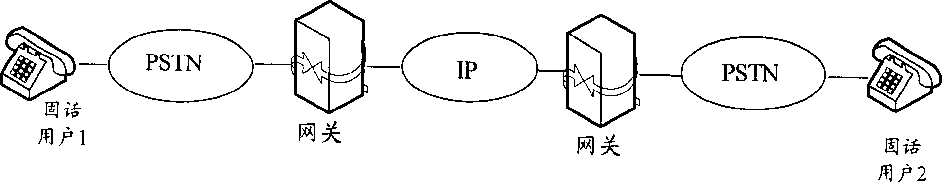
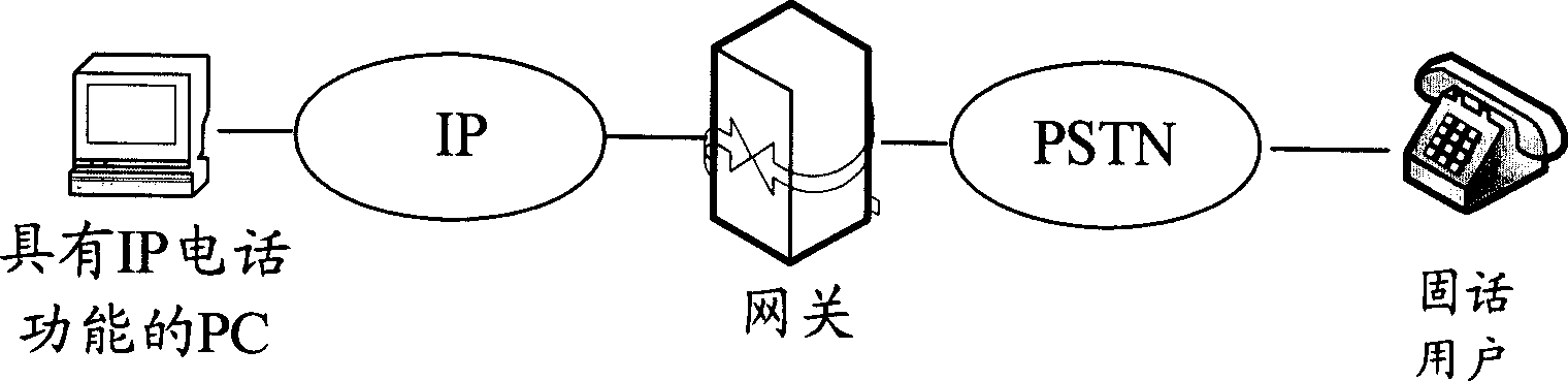
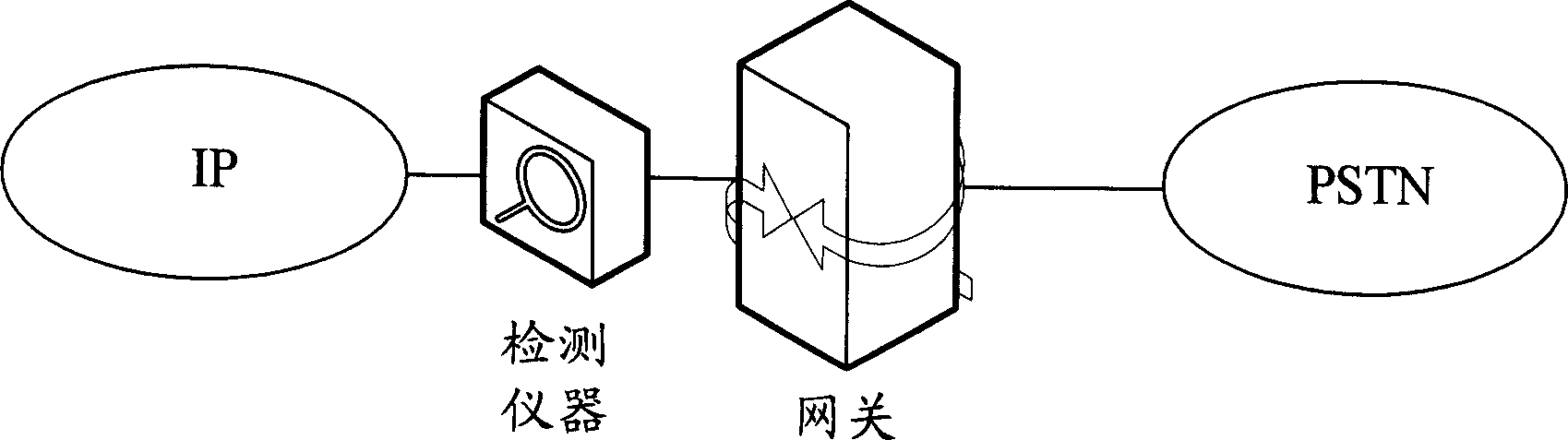
[0032] Based on the above ideas, the present invention provides a method for detecting signal transmission channels, the core of which is: at the four-wire relay side of the PSTN exchange, the voice signal from the gateway is obtained; The specific gravity is greater than the preset threshold; then it is judged that the front end of the voice signal is transmitted via the IP network, PLMN network, satellite network and other v...


PUM


Abstract

This invention relates to a method for testing phone signal transmission channels and a call control system, in which, said method includes: obtaining phone signals from the gateway at the fourth line side of the PSTN exchanger, if the PSTN channel stipulated by the national standard and related standard is forbidden to carry the energy gravity larger than a preset threshold, then it is decided that the front of the phone signal is converted from a parameter code to G711 code or transmitted by the IP communication network applying parameter code technology, otherwise, it is judged that said front is transmitted in the PSTN.

Description

technical field [0001] The invention relates to signal transmission channel detection technology, in particular to a transmission channel detection method capable of IP phone feature detection and a call control system adopting the method. Background technique [0002] With the rapid development of Internet networks and services, and the continuous improvement of voice technology based on Internet Protocol (VoIP, Voice over internet protocol), the development of VoIP services is increasingly emerging. The VoIP technology is a packetization and digital transmission technology based on the IP technology. Its basic principle is: compress and code the voice through the voice compression algorithm, then pack the voice data according to IP and other related protocols, and pass through the IP network The data packets are transmitted to the destination, and then these voice data packets are stringed together. After decoding and decompression processing, the original voice signals ar...

Claims


Application Information

Patent Timeline
IPC IPC(8): H04M3/22H04M7/00H04L29/06
Inventor 彭煊吉立新王炳锡王波陈鸿昶
Owner THE PLA INFORMATION ENG UNIV
Why Eureka
Try Eureka