Interlocking intramedullary pin with elastic dynamic interlocking pin

An intramedullary nail and interlocking technology, which is applied in the field of interlocking intramedullary nails, can solve the problems of prolonged fracture healing time and stress shielding of fracture ends, so as to shorten the healing period, reduce pain and pain, and prevent bone shortening Effect

Inactive Publication Date: 2006-11-01
张国辉
View PDF1 Cites 1 Cited by
  • Summary
  • Abstract
  • Description
  • Claims
  • Application Information

AI Technical Summary

Problems solved by technology

[0006] In order to solve the existing conventional interlocking intramedullary nails in the clinical application of the fracture end of the stress shielding, fracture healing time prolongation and other problems

Method used


Image

  • Interlocking intramedullary pin with elastic dynamic interlocking pin
  • Interlocking intramedullary pin with elastic dynamic interlocking pin
  • Interlocking intramedullary pin with elastic dynamic interlocking pin

Examples


Embodiment Construction

[0027] The following examples are used to illustrate the present invention, but are not intended to limit the scope of the present invention. In order to describe the present invention more clearly, in view of the apparatus and components used are well known to those skilled in the art, each accessory will not be described in detail here, and its structural composition will be combined with the following embodiments, and The overall operation and usage are explained as follows:

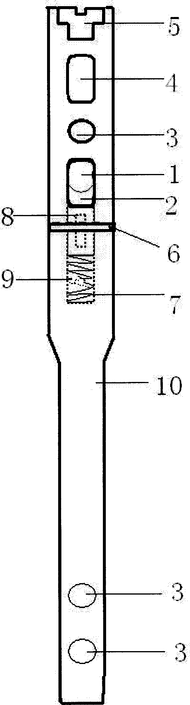
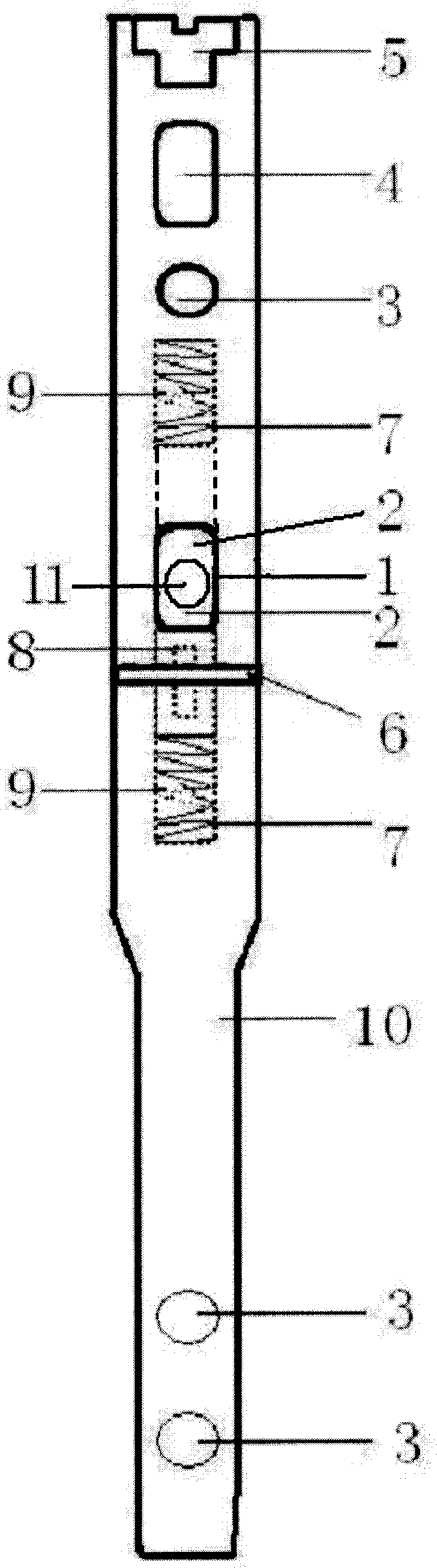
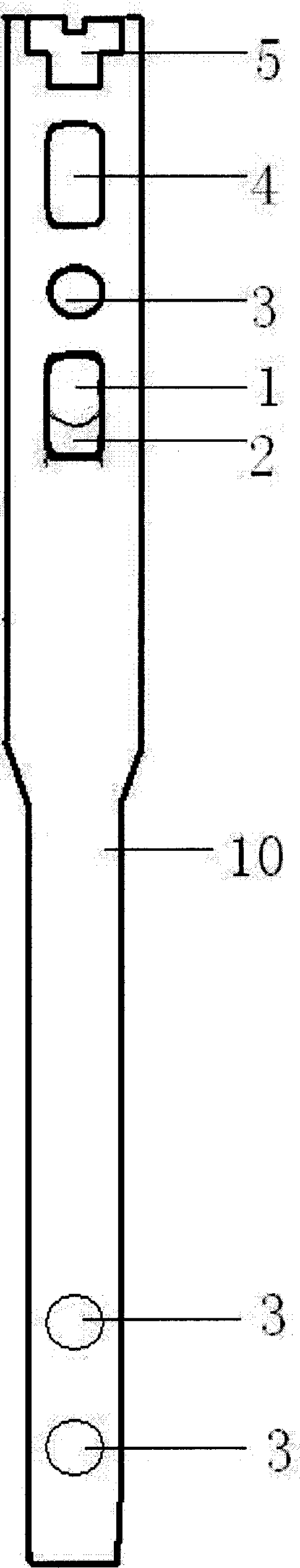
[0028] against figure 1 , image 3 ,by figure 1 Take this as an example. figure 1 The structure of the sectional view is as follows: the nail body 10 has the following structure and has the following accessories: elastic dynamic interlocking hole 1, static interlocking hole 3, dynamic interlocking hole 4 and tail cap 5.

[0029] With the hollow nail body 10, put the elastic device 9 in it (the bottom end of its hollow part is the dark groove 7, and the solid nail can be loaded into the elastic dev...


PUM


Abstract

An interlocking intramedullary nail for treating bone fracture of leg is characterized by that it has elastic dynamic interlocking hole, several static interlocking holes, dynamic interlocking hole, and tail cap. It can speed up the healing of bone.

Description

(1) Technical field [0001] The invention relates to an interlocking intramedullary nail, in particular to an interlocking intramedullary nail with elastic and dynamic interlocking holes. It belongs to the field of medical equipment. (2) Background technology [0002] In the prior art, an interlocking intramedullary nail is a medical device commonly used in the field of medical devices for post-fracture treatment. There are many types of intramedullary nails, such as Ender nails, self-locking intramedullary nails, rectangular nails, and interlocking intramedullary nails. Among them, the advantages of Ender nails, self-locking intramedullary nails, and rectangular nails are the advantages of elastic fixation of intramedullary nails, no stress shielding, and early fracture healing; the disadvantages are poor anti-rotation and anti-shortening capabilities, limited surgical indications, and discomfort For early functional exercise, some cases need auxiliary external fixation in...

Claims


Application Information

Patent Timeline
Patent Type & Authority Applications(China)
IPC IPC(8): A61B17/72
Inventor 张国辉
Owner 张国辉
Why Eureka
Try Eureka