

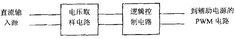
Input under-voltage/over-voltage protection circuit
An overvoltage protection circuit, input undervoltage technology, applied in the protection of undervoltage or no voltage reaction, overvoltage reaction protection, etc., can solve the problems of program confusion, wrong timing, latch-up, etc., to achieve The effect of preventing program confusion
- Summary
- Abstract
- Description
- Claims
- Application Information
AI Technical Summary
Problems solved by technology
Method used
Image

Examples
Embodiment 1
[0053] Such as Figure 4 As shown, an input undervoltage or overvoltage protection circuit of the present invention includes a voltage sampling circuit 1, a logic control circuit 2, a hysteresis control circuit 3, and a sampling output holding circuit 4.
[0054] Such as Figure 7 As shown, the voltage sampling circuit 1 is a series branch composed of a first resistor R1 and a first Zener diode D1. One end of the first resistor R1 is connected to the direct current input source DC, and the other end is connected to the cathode of the first Zener diode D1. The other end of the first Zener diode D1 serves as the output end of the voltage sampling circuit 1. The logic control circuit 2 includes a second resistor R2, a third resistor R3, a fourth resistor R4, a first switch tube Q1, and a second switch tube Q2. One end of the second resistor R2 is connected to one end of the third resistor R3 and then connected to the direct current input source DC. One end of the fourth resistor R...
Embodiment 2
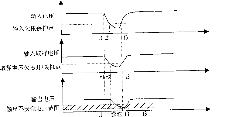
[0061] Such as Picture 10 As shown, compared with the first embodiment, this embodiment only removes the sample output holding circuit 4. Among them, the working principle of the hysteresis control circuit 3 is (take undervoltage protection as an example): when the input voltage is low (below the input undervoltage point), the first zener diode D1 and the second zener diode D2 are not conducting , The first switching tube Q1 is turned off, Q2 is turned on, the PWM control pin is pulled low, the PWM has no output, and it is in the undervoltage protection state. The collector voltage of the Q2 tube is low, the Q3 tube does not conduct, and the voltage regulator tube D2 is not bypassed. When the input voltage is greater than the regulated voltage of the regulator tubes D1 and D2 plus the sum of the conduction voltage drop of the Q1 tube base V D1 +V D2 +V beQ1 At this time, the Q1 tube is turned on, the Q2 tube is off, and the Q3 tube is turned on, the circuit starts to start, a...
Embodiment 3
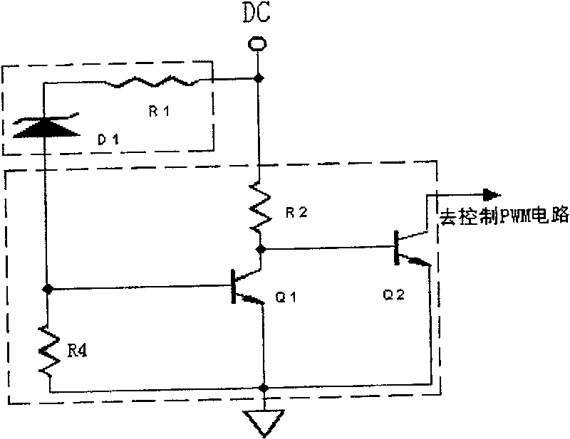
[0063] Such as Picture 11 As shown, an input under-voltage or over-voltage protection circuit includes a voltage sampling circuit 1, a logic control circuit 2 and a sampling output holding circuit 4.
[0064] The voltage sampling circuit 1 is a series branch composed of a first resistor R1 and a first Zener diode D1. One end of the first resistor R1 is connected to the direct current input source DC, and the other end is connected to the cathode of the first Zener diode D1. The other end of the first Zener diode D1 serves as the output end of the voltage sampling circuit 1. The logic control circuit 2 includes a second resistor R2, a fourth resistor R4, a first switch tube Q1, and a second switch tube Q2. One end of the second resistor R2 is connected to the DC input source. One end of the fourth resistor R4 is connected to the base of the first switching tube Q1 as the input end of the logic control circuit 2 and is connected to the output end of the voltage sampling circuit ...
PUM
 Abstract
Description
Claims
Application Information