Gas Cooling and Heat Utilization Devices for Concentrating Solar Energy Systems

A concentrating solar energy and gas cooling technology, applied in the field of photovoltaics, can solve the problems of decreased transmittance of optical systems, decreased system efficiency, affecting the working state of photovoltaic modules, etc., to achieve the effect of increasing energy utilization channels and improving energy utilization rate

Active Publication Date: 2015-09-30
广东明阳光伏产业有限公司
View PDF8 Cites 0 Cited by
  • Summary
  • Abstract
  • Description
  • Claims
  • Application Information

AI Technical Summary

Problems solved by technology

[0005] However, the working life of the breathable waterproof and dustproof material used in the ventilation window is very limited, and it is difficult to meet the working life (25 years) requirements of the photovoltaic power generation system.
And under some extreme weather conditions, it is easy to be damaged or suffer local damage, allowing foreign particles, water vapor or grease to enter, destroying the working environment of the system, reducing the transmittance of the optical system, damaging the electrical connection and causing Corrosion and oxidation of the core components of the system, causing irreversible damage
In addition, the ventilation window area is usually very small, and in order to ensure waterproof and dustproof requirements, its ventilation capacity is very limited, which can only meet the needs of balancing the internal and external pressure differences, and it is difficult to make the gas flow inside and outside the box, and the modules accumulate under sunlight. Not only can the heat not be utilized, but it will also increase the internal working temperature of the box, affecting the working state of the photovoltaic module, reducing the system efficiency and shortening the life span.

Method used


Image

  • Gas Cooling and Heat Utilization Devices for Concentrating Solar Energy Systems
  • Gas Cooling and Heat Utilization Devices for Concentrating Solar Energy Systems
  • Gas Cooling and Heat Utilization Devices for Concentrating Solar Energy Systems

Examples


Embodiment 1

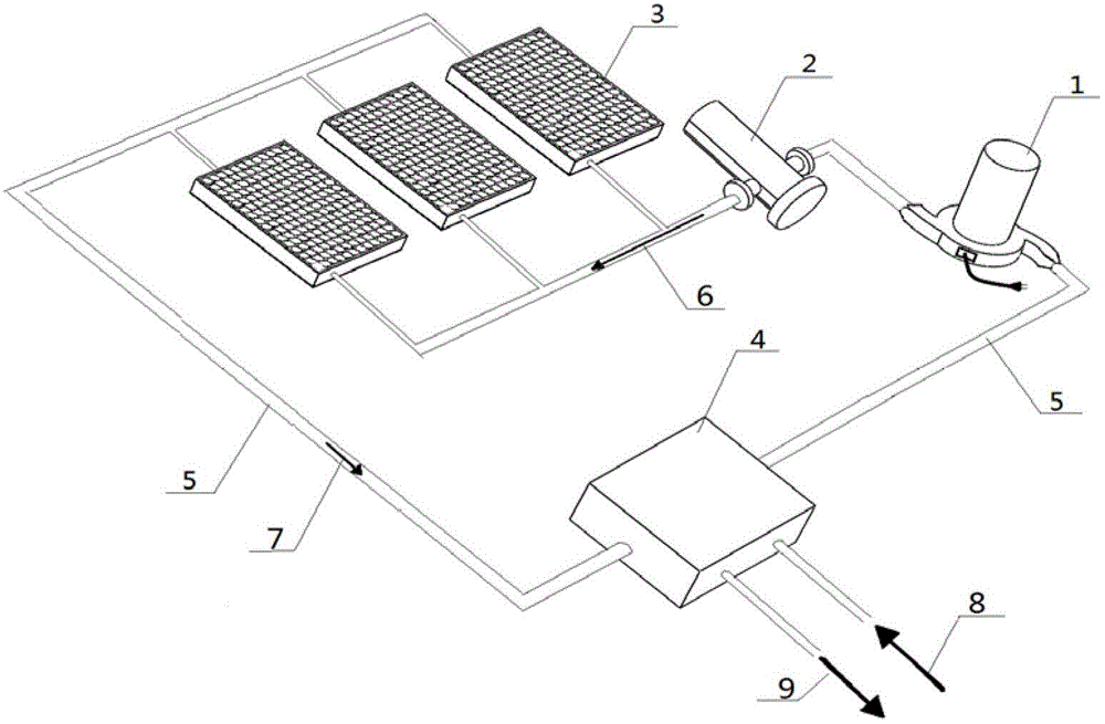
[0029] For details, see figure 1 , there are three concentrating solar cabinets 3, the concentrating solar cabinets 3 are connected to the gas filter 2 and the gas heat utilization device 4 through the gas pipeline 5, and the three concentrating solar cabinets 3 are connected in parallel , the gas filter 2 is connected to the gas driver 1 through the gas pipeline 5 , and the other end of the gas driver 1 is connected to the gas heat utilization device 4 through the gas pipeline 5 . The gas heat utilization device of this embodiment is a device for heating cold water by utilizing heat exchange between hot gas and cold water. In addition, due to the small number of concentrating solar energy cabinets 3 in this embodiment, the heat flow effect caused by the heating of the gas in the cabinet is not obvious. In order to meet the needs of gas flow and filtration, a gas driver 1 is used to make the gas circuit A pressure difference is generated at both ends of the gas driver 1 to dr...

Embodiment 2

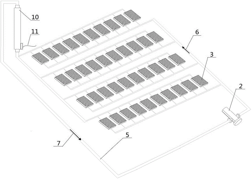
[0033] See Example 2 figure 2 . In this embodiment, there are four groups of concentrating solar energy cabinets, and each group contains ten concentrating solar energy cabinets 3 . Four groups of concentrating solar cabinets and each group of ten cabinets are connected in parallel through gas pipelines 5 . Four groups of concentrating solar energy boxes 3 are connected with the gas filter 2 and the blade generator 10 through the gas pipeline 5 . In this embodiment, due to the large number of concentrating solar energy boxes in the gas circuit, the thermal expansion of the gas in the box and the gas flow effect will be more obvious, and the blade generator 10 can be directly driven to generate electricity.

[0034] figure 2 In the above, when the concentrating solar energy box 3 works under sunlight, the gas in the box expands after being heated, and will flow out from the gas pipeline interface at the upper end of the box. After the gas is merged, the gas continues to f...

Embodiment 3

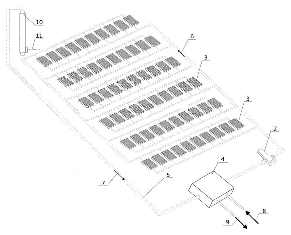
[0037] Example three see image 3 . In this embodiment, there are six groups of concentrating solar cabinets, and each group contains ten concentrating solar cabinets 3 . The six groups of concentrating solar cabinets and each group of ten cabinets are connected in parallel through the gas pipeline 5 . Six groups of concentrating solar panels 3 are connected to the gas filter 2 and the blade generator 10 through the gas pipeline 5 , and the gas filter 2 and the blade generator 10 are connected to the gas heat utilization device 4 through the gas pipeline 5 . In this embodiment, due to the large number of connected boxes, the thermal expansion of the gas in the box and the gas flow effect due to the expansion of the gas will be more obvious, and the blade generator 10 can be directly driven to generate electricity, and the gas heat utilization device 4 can also be used for cooling. Heat exchange to obtain hydrothermal output.

[0038] image 3 Among them, when the concentra...


PUM


Abstract

The invention provides a gas-cooling and heat-utilizing device of a concentrating solar system and relates to the field of photovoltaic technology. The gas-cooling and heat-utilizing device of the concentrating solar system concretely comprises a gas filter (2), a concentrating solar box body (3), a gas driver (1) and\or a blade generator (10), a gas pipeline (5) and a gas heat utilizing device (4), wherein the concentrating solar box body (3) is arranged in a serial, parallel or multi-stage parallel form in the gas pipeline (5), and forms a closed or quasi closed gas loop together with the gas driver (1) and\or a blade generator (10), the gas filter (2) and the gas heat utilizing device (4) through the gas pipeline (5). The technical problem to be solved by the invention is providing the gas-cooling and heat-utilizing device of the concentrating solar system, which is used for keeping high sealing property and high cleanness of the entire gas loop, and pollutants such as external dust, grease and water vapor are prevented from entering into a concentrating solar box body.

Description

technical field [0001] The invention relates to the field of photovoltaic technology, in particular to a gas cooling and heat utilization device for a concentrated solar system. Background technique [0002] At present, the third-generation photovoltaic power generation technology represented by concentrating photovoltaic power generation (HCPV) is experiencing rapid development, and its related technologies have become research and development hotspots of various research institutes and enterprises. Various concentrating photovoltaic demonstration projects and large-scale power stations It is also appearing all over the world. As far as its main principle is concerned, concentrating photovoltaic power generation technology (CPV) refers to the use of lenses or mirrors to focus the received sunlight, so that the focused high-energy-density light spot is aligned on a small-area, high-efficiency silicon or polycarbonate. Combine compound solar cell chips to obtain energy outpu...

Claims


Application Information

Patent Timeline
Patent Type & Authority Patents(China)
IPC IPC(8): H02S40/42H02S40/44H01L31/048H01L31/0525H01L31/055
CPCY02E10/50Y02E10/60Y02E10/40Y02E10/52
Inventor 王智勇陈丙振杨光辉
Owner 广东明阳光伏产业有限公司
Why Eureka
Try Eureka