Decoding device and method

A decoding device and decoding technology, which are applied in the field of decoding devices and decoding, can solve the problems of synchronization code pseudo-synchronization and synchronization deviation, deviation, synchronization code false detection, false synchronization and synchronization, etc.

Inactive Publication Date: 2007-02-14
KK TOSHIBA
View PDF0 Cites 2 Cited by
  • Summary
  • Abstract
  • Description
  • Claims
  • Application Information

AI Technical Summary

Problems solved by technology

[0017] The main purpose of the present invention is to provide an encoding device and a decoding device that can solve the problems of false synchronization and synchronization deviation caused by misdetection of synchronization codes
[0018] A more specific object of the present invention is to provide an encoding device and an encoding device capable of solving the problems of false synchronization and synchronization deviation caused by misdetection of synchronization codes when error correction / detection encoding is combined with a synchronization recovery method using synchronization codes. decoding device

Method used


Image

  • Decoding device and method
  • Decoding device and method
  • Decoding device and method

Examples


Embodiment 1

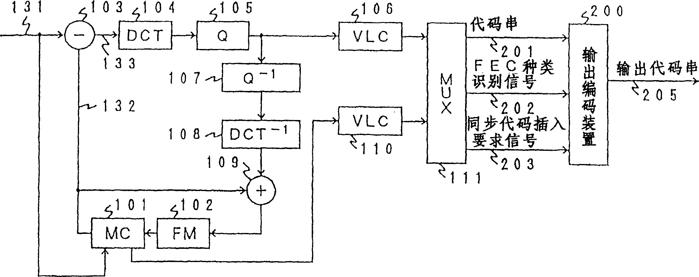
[0095] figure 1 It represents the moving image coding that combines the coding device having the error correction / detection code switching function of the present invention with a high-efficiency compression coding device that uses motion compensation adaptive prediction and orthogonal transform coding, that is, discrete cosine transform coding. Block diagram of Example 1 of the device. Regarding the coding method combining motion compensation adaptive prediction and discrete cosine transform coding, for example, there are detailed descriptions in Document 1: Edited by Hiroshi Yasuda, "International Standards for the Symbolization of Malchi Media", Maruzen, (June 2013), etc. Note, therefore, only an overview of the action is described here. In addition, the error correction / detection codes used in this embodiment are codes separated into information bits and check bits like BCH codes.

[0096] exist figure 1In this method, the input moving image signal 131 to be coded in ...

Embodiment 2

[0168] Below, refer to Figure 12 to Figure 14 Example 2 of the present invention will be described. Even if the moving image encoding device and moving image decoding device of the present embodiment use a transmission path / storage medium in which a part of a bit sequence is eliminated to reduce the number of bits or add extra bits to increase the number of bits, the code sequence is transmitted / stored. , can also be reliably detected synchronously.

[0169] Figure 12 It is a block diagram showing the principle of the synchronization detection processing at the time of such bit addition / deletion. here, as Figure 12 As shown in (a), the correct synchronization code is composed of "0" of sync_0_len bit and "1" of 1 bit. Figure 12 The "×" in is a bit other than the synchronization code.

[0170] Figure 12 (b) to (e) show how the synchronization code changes due to bit addition / deletion. Here, the number of bits (Nid) to be added / disappeared is 1 bit at most. (b) is a...

Embodiment 3

[0218] Next, Embodiment 3 of the present invention will be described. The difference between this embodiment and Embodiment 1 and Embodiment 2 is that no error correction / detection code is used.

[0219] Figure 18 It is a block diagram of the video coding apparatus of this embodiment. right with figure 1 Corresponding parts are denoted by the same symbols and will be described focusing on differences from Embodiment 1. In this embodiment, the structure and operation of the output encoding device 200 are different. In addition, the basic actions of multiplexer 111 and figure 1 The multiplexer 111 is the same, however, as the error correction / detection code is not used, only the multiplexed code string 201 and the synchronous code insertion request signal 203 are output.

[0220] Figure 19 yes means Figure 18 A block diagram of the structure of the output encoding device 200 in FIG. The output encoding device 200 is composed of a counter 1701 for counting the number ...


PUM


Abstract

The problems of pseudo-synchronization and out-of synchronization caused by erroneous detection of synchronization codes of an encoder in which an error correction / detection coding and a synchronism restoring method using synchronization codes. There are provided a coding unit (212) for encoding a sequence of inputted multiplex codes (201 ) into error correction / detection codes comprising information bits and inspection bits; and a code sequence assembling unit (213) for assembling a sequence of output codes (205) by inserting a synchronization code into any of a plurality of periodically predetermined synchronization code insertion positions in the code sequence (201) and by arranging the information bits in arbitrary positions in the code sequence and the inspection bits in positions other than the synchronization code insertion positions in the code sequence (201).

Description

[0001] This application is a divisional application of the Chinese patent application with the application number 97193909.8 and the title of the invention "encoding device and decoding device" submitted by the same applicant on March 18, 1997. technical field [0002] The present invention relates to a system for transmitting / storing information through a medium with a high bit error rate such as a wireless transmission line, and a decoding device for performing error correction / detection coding on a compressed code string obtained by high-efficiency compression coding and transmitting / storing it / decoding method. Background technique [0003] For example, as in wireless television (TV) telephones, portable information terminals, and digital TV broadcasting systems, it is necessary to efficiently compress and encode and transmit through wireless transmission lines to reduce image and sound information to as little information as possible. In the system, due to the high bit ...

Claims


Application Information

Patent Timeline
Patent Type & Authority Applications(China)
IPC IPC(8): H04L7/08H04N7/64H04L1/00H03M7/30H04N19/89
Inventor 菊地义浩渡边敏明驮竹健志中条健永井刚
Owner KK TOSHIBA
Why Eureka
Try Eureka