Coding device and coding method
A decoding device and decoding technology are applied in the field of decoding devices and decoding, and can solve the problems of false synchronization and synchronization of synchronization code error detection, pseudo synchronization of synchronization code and synchronization deviation, deviation and the like
- Summary
- Abstract
- Description
- Claims
- Application Information
AI Technical Summary
Problems solved by technology
Method used
Image
Examples
Embodiment 1
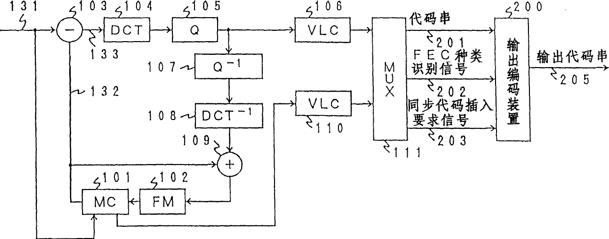
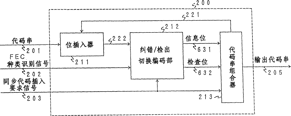
[0097] FIG. 1 is a motion diagram showing a combination of an encoding device having an error correction / detection code switching function of the present invention and a high-efficiency compression encoding device using discrete cosine transform encoding, which is one of motion compensation adaptive prediction and orthogonal transform encoding. A block diagram of Embodiment 1 of the image encoding device. Regarding the encoding method combining adaptive prediction with motion compensation and discrete cosine transform encoding, for example, there are detailed descriptions in Document 1: Edited by Hiroshi Yasuda, "International Standards for Symbolization of Malchi Media", Maruzen, (June 2013), etc. Note, therefore, only an overview of the action is described here. In addition, the error correction / detection codes used in this embodiment are codes separated into information bits and check bits like BCH codes.
[0098] In FIG. 1, an input video signal 131 to be coded which is i...
Embodiment 2
[0171] Next, Embodiment 2 of the present invention will be described with reference to FIGS. 12 to 14 . Even if the moving image encoding device and moving image decoding device of the present embodiment use a transmission path / storage medium in which a part of a bit sequence is eliminated to reduce the number of bits or add extra bits to increase the number of bits, the code sequence is transmitted / stored. , can also be reliably detected synchronously.
[0172] FIG. 12 is a block diagram showing the principle of processing for synchronous detection at the time of such bit addition / deletion. Here, as shown in FIG. 12( a ), a correct synchronization code is composed of "0" of sync_0_len bits and "1" of 1 bit. "X" in FIG. 12 is a bit other than the synchronization code.
[0173] 12(b) to (e) show how the synchronization code changes due to bit addition / deletion. Here, the number of bits (Nid) to be added / disappeared is 1 bit at most. (b) is a case where one bit is deleted in...
Embodiment 3
[0221] Next, Embodiment 3 of the present invention will be described. The difference between this embodiment and Embodiment 1 and Embodiment 2 is that no error correction / detection code is used.
[0222] Fig. 18 is a block diagram of the moving picture coding apparatus of this embodiment. Parts corresponding to those in FIG. 1 are denoted by the same reference numerals and will be described focusing on differences from Embodiment 1. In this embodiment, the structure and operation of the output encoding device 200 are different. The basic operation of the multiplexer 111 is the same as that of the multiplexer 111 in FIG. 1, but only the multiplexed code string 201 and the synchronization code insertion request signal 203 are output as the error correction / detection code is not used.
[0223]FIG. 19 is a block diagram showing the configuration of the output encoding device 200 in FIG. 18 . The output encoding device 200 is composed of a counter 1701 for counting the number of ...
PUM
 Abstract
Description
Claims
Application Information
 - R&D
- Intellectual Property
- Life Sciences
- Materials
- Tech Scout
- Unparalleled Data Quality
- Higher Quality Content
- 60% Fewer Hallucinations
Browse by: Latest US Patents, China's latest patents, Technical Efficacy Thesaurus, Application Domain, Technology Topic, Popular Technical Reports.
© 2025 PatSnap. All rights reserved.Legal|Privacy policy|Modern Slavery Act Transparency Statement|Sitemap|About US| Contact US: help@patsnap.com


