Multi-stage oil-less gas compressor

A screw compressor and compressor technology, which is applied in the direction of liquid variable volume machinery, mechanical equipment, variable volume pump components, etc., to achieve the effect of reducing costs and high heat exchange rate

Inactive Publication Date: 2007-02-21
科拉克能源技术有限公司
View PDF1 Cites 6 Cited by
  • Summary
  • Abstract
  • Description
  • Claims
  • Application Information

AI Technical Summary

Problems solved by technology

This has issues related to balance and bearing, as balancing accuracy needs to be increased, and speeds exceed traditional bearing capabilities

Method used


Image

  • Multi-stage oil-less gas compressor

Examples


Embodiment Construction

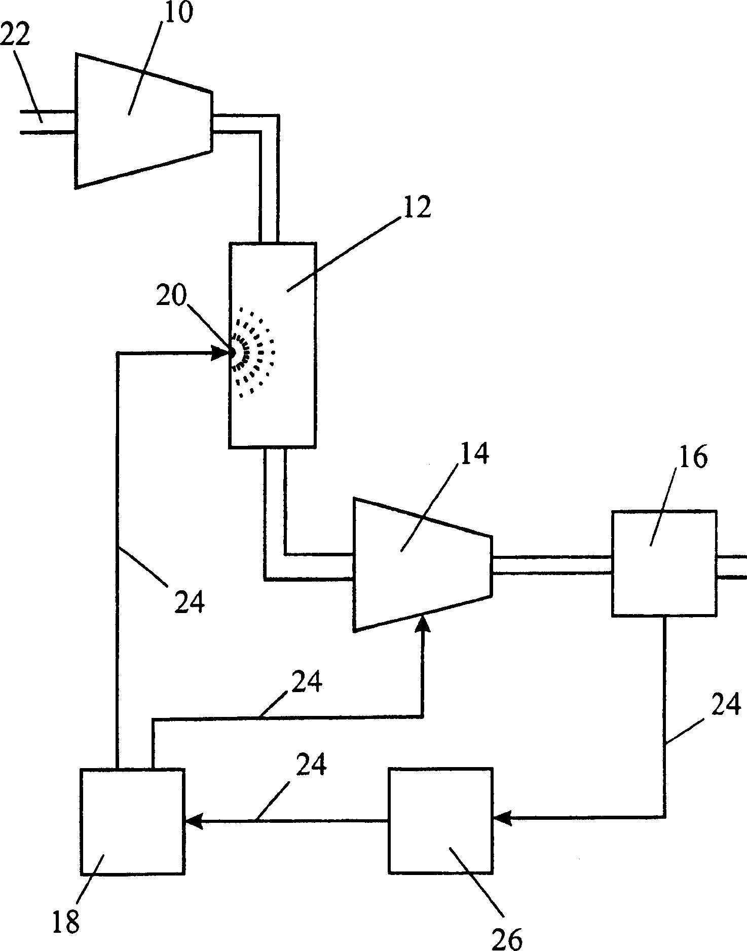
[0019] In the only figure, the ducts along which the gas flows are shown with double lines, while the pipes for carrying water, indicated at 24, are shown with one line.

[0020] The gas to be compressed enters the electrically driven centrifugal compressor 10 at 22 . Once compressed by centrifugal compressor 10 , the hot gas flows through water jet intercooler 12 .

[0021] The water jet intercooler 12 is actually a tank that slows down the gas. Simultaneously, water is sprayed into the tank through nozzles or injectors 20 at high pressure. These cause the water to be atomized into a fine mist which cools the now slowed moving gas giving the water more time to absorb heat from the gas. Adjust the water flow velocity in the intercooler and the droplet size of the jet to ensure that the heat of compression of the gas is accepted by the cooling water. This method of cooling avoids the use of heat exchangers, which are bulky, expensive, create pressure drops, and are prone to ...


PUM


Abstract

An air compressor of multistage and oil free type consists of dynamic compress or stage of speed variable and motor driven rotation mode being series-connected with water lubricating screw compressor stage at upstream of water lubricating screw compressor, intermediate cooler being set between two said compressor stages for deceasing temperature of air entering into screw compressor stage.

Description

technical field [0001] The invention relates to a multi-stage oil-free gas compressor with an intermediate cooling device. Background technique [0002] There are many techniques that can be used to compress gases, each with its advantages in terms of total pressure rise, volumetric flow rate achievable, and efficiency of the process work. [0003] Rotodynamic compressors include axial compressors and centrifugal compressors, which can achieve gas compression by using high-speed rotors, thereby increasing the momentum of the gas, which is converted into pressure head. This machine is ideal when high volume flow is required with relatively low inlet pressure. To increase outlet pressure, greater rotational speeds are required, which becomes difficult to achieve while maintaining acceptable efficiencies relative to other methods. These machines are usually oil-free because the working elements do not come into contact with oil lubricants. It is important that these processe...

Claims


Application Information

Patent Timeline
Patent Type & Authority Applications(China)
IPC IPC(8): F04B41/06F04B37/12F04B39/06
Inventor A·阿尔弗德G·W·克罗姆J·O·里德
Owner 科拉克能源技术有限公司
Why Eureka
Try Eureka