Condenser

A technology of condenser and condensate, applied in the direction of evaporator/condenser, refrigerator, refrigeration components, etc., can solve problems such as hindering heat transfer, and achieve the effect of small pressure loss and large effect

Active Publication Date: 2017-12-01
EBARA REFRIGERATION EQUIP & SYST CO LTD
View PDF8 Cites 3 Cited by
  • Summary
  • Abstract
  • Description
  • Claims
  • Application Information

AI Technical Summary

Problems solved by technology

That is, since the refrigerant liquid condensed in the upper heat transfer tube of one heat transfer tube group flows down to the lower heat transfer tube, the liquid refrigerant liquid on the surface of the lower heat transfer tube The film becomes thicker, so there is a problem of hindering heat transfer

Method used


Image

  • Condenser
  • Condenser
  • Condenser

Examples


Embodiment Construction

[0053] Below, refer to Figure 1 to Figure 15 Embodiments of the condenser of the present invention will be described. exist Figure 1 to Figure 15 In , the same reference signs are attached to the same or corresponding constituent elements, and overlapping descriptions are omitted. In the present embodiment, the condenser is described as a condenser for a refrigerator, but it can also be used for condensing water vapor or vapor of a chemical substance. In addition, in this embodiment, a turbo refrigerator will be described as an example of a refrigerator.

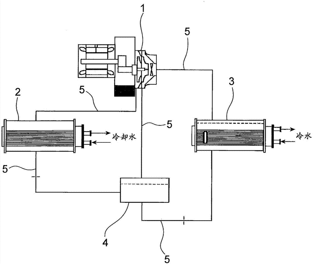
[0054] figure 1 It is a schematic diagram showing a turbo refrigerator equipped with the condenser of the present invention. Such as figure 1 As shown, the turbo refrigeration mechanism has: a turbo compressor 1, which compresses the refrigerant; a condenser 2, which uses cooling water (cooling fluid) to cool and condense the compressed refrigerant gas; an evaporator 3, It takes heat from the cold water (cooled fluid...


PUM


Abstract

The condenser provided by the present invention can smoothly supply the refrigerant vapor (condensed fluid vapor) to the heat transfer tube and can reduce the pressure loss and reduce the liquid film of the condensate on the surface of the heat transfer tube to improve the heat transfer performance. The condenser (2) includes a cylindrical can body (11), tube sheets (12,12) closing both ends of the can body (11), and at least one heat transfer tube(14) disposed in the can body (11) for exchanging heat between the condensed fluid vapor introduced into the tank (11) and the cooling fluid flowing through the heat transfer tube group (14) to condense the condensed fluid vapor to condense in the condenser(2) Is provided with a liquid-containing member (20) which is a member extending in the longitudinal direction of the can body (11) and receives the condensed liquid condensed by the condensed liquid.

Description

technical field [0001] The condenser according to the present invention is equipped with at least one heat transfer tube group in the tank body, and heat exchange is performed between the condensed fluid vapor introduced into the tank body and the cooling fluid circulating in the heat transfer tube group, so that the condensed fluid Steam condenses. Background technique [0002] Conventionally, compression refrigerating machines such as turbo refrigerating machines used in refrigerating and air-conditioning equipment etc. are constructed by connecting an evaporator, a compressor, a condenser, and an expansion valve (expansion mechanism) through refrigerant piping. The airtight system structure of the agent takes heat from the cold water (fluid to be cooled) and evaporates the refrigerant to exert the cooling effect. The compressor compresses the refrigerant gas evaporated by the evaporator to become a high-pressure refrigerant gas. The condenser cools high-pressure refriger...

Claims


Application Information

Patent Timeline
Patent Type & Authority Applications(China)
IPC IPC(8): F25B39/04
CPCF25B39/04F25B2339/046
Inventor 山田宏幸石山健天野俊辅
Owner EBARA REFRIGERATION EQUIP & SYST CO LTD
Why Eureka
Try Eureka