Gas-liquid separating device

A gas-liquid separation device and a technology for gas-liquid separation, which are applied to the separation device of liquid two-phase and gas field, can solve the problems of unsatisfactory requirements, difficult cleaning and maintenance, low separation efficiency, etc., and achieve reliable effect, stable structure, The effect of reducing the motion section

Active Publication Date: 2013-01-16
兰州节能环保工程有限责任公司 +1
View PDF3 Cites 32 Cited by
  • Summary
  • Abstract
  • Description
  • Claims
  • Application Information

AI Technical Summary

Problems solved by technology

However, these separation devices often use multiple baffles and small cross-sections to achieve gas-liquid separation, which will cause a large pressure loss, and the separation efficiency is generally not high, which cannot meet the ideal requirements, and a large number of separation devices use thin steel wires or thin plates. Made of high-quality materials, the reliability of the equipment is not high, and it is difficult to clean and maintain

Method used


Image

  • Gas-liquid separating device
  • Gas-liquid separating device

Examples


Embodiment Construction

[0014] The present invention is explained below with reference to the drawings and embodiments.

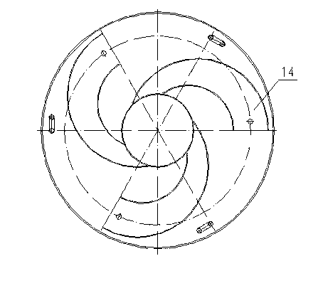
[0015] In this embodiment, the number of centrifuge cylinders is set to three, which are evenly arranged in a circle.

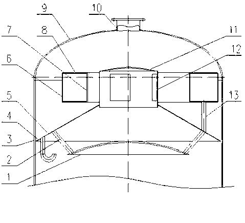
[0016] In evaporators that are widely used, the quality requirements for secondary steam are also very high, because relatively pure secondary steam can improve equipment thermal efficiency, extend equipment service life, reduce water hammer, and obtain ideal secondary condensate. Therefore, the role of the gas and liquid separation device is very critical. The gas-liquid separation device of the present invention is generally arranged on the top of the vapor-liquid evaporation equipment (such as air conditioner, compressor, tower or evaporator) to be separated, fixed in a stepped manner, and communicated with the secondary vapor exhaust port.

[0017] In the present invention, an exhaust port 10 is provided on the upper part of the head 9. A cylindrical structure 3 i...


PUM


Abstract

The invention discloses a device for separating a gas phase and a liquid phase in an air conditioner, a compressor, a tower, or an evaporator. The device comprises a shell cover, a cylindrical structure, and a flow baffling cover, a flow guide conical surface, a flow distributing cylinder, centrifugal channels, a liquid discharge pipe and an exhaust port, wherein the cylindrical structure is arranged below the shell cover, the flow baffling cover and the flow guide conical surface are arranged in the device, the flow distributing cylinder is provided with a top cover, the exhaust port is arranged on the shell cover and is communicated with the external world; the lower bottom of the flow guide conical surface is fixed on the inner wall of the cylindrical structure; the bottom of the flow distributing cylinder is fixed on the top of the flow guide conical surface; the flow baffling cover is fixed on the lower part of the flow guide conical surface through a connecting rod; at least two rectangular holes are equidistantly formed in the side wall of the flow distributing cylinder; the centrifugal channels are arranged at each of the rectangular holes, wherein a section of each of the centrifugal channels is a rectangular expanded section, and the centrifugal channels are arranged along the tangential direction of the flow distributing cylinder; and a liquid channel communicating the upper part and the lower part of a flow guide cone is arranged at the bottom of the flow guide conical surface.

Description

technical field [0001] The invention relates to a gas-liquid two-phase separation device in industrial equipment, in particular to a gas-liquid separation device used in air conditioners, compressors, towers or evaporators. The invention comprises: a head, a cylindrical structure located under the head, a choke cover located in the device, a diversion cone, a shunt tube with a top cover, a centrifugal channel, a drain pipe and a pipe arranged on the head Exhaust ports that communicate with the outside world, etc. Background technique [0002] The gas-liquid separation device has a wide range of applications in modern industrial production. For example, the secondary steam generated during the working process of the evaporation system is often used as the heat source of the next-effect evaporation equipment, but it often contains a large number of tiny droplets and other components. , mixes in the secondary steam and flows with it, if it cannot be effectively removed, it w...

Claims


Application Information

Patent Timeline
Patent Type & Authority Applications(China)
IPC IPC(8): B01D45/16B01D45/02B01D45/00
Inventor 张培洲邵珲盖美萍张锐
Owner 兰州节能环保工程有限责任公司
Why Eureka
Try Eureka