Diffusion-type self-pumped fluid dynamic and static pressure mechanical seal

A mechanical seal, dynamic and static pressure technology, applied to the sealing of the engine, mechanical equipment, engine components, etc., can solve the problems of low pressure bearing capacity, small rigidity, affecting safety, etc., and achieve the effect of increasing the opening force

Active Publication Date: 2021-06-15
NANJING FORESTRY UNIV
View PDF9 Cites 4 Cited by
  • Summary
  • Abstract
  • Description
  • Claims
  • Application Information

AI Technical Summary

Problems solved by technology

However, the self-pumping hydrodynamic mechanical seal solves the problem of blocking the supply subsystem of the fluid, but its disadvantage of small stiffness affects the safety of operation; and the newly proposed magnetic fluid seal and self-pumping hydrodynamic mechanical seal The combined non-contact double-face seal has too low pressure bearing capacity and is not suitable for use as a shaft seal for low- and medium-speed rotating machinery such as centrifugal pumps.

Method used


Image

  • Diffusion-type self-pumped fluid dynamic and static pressure mechanical seal
  • Diffusion-type self-pumped fluid dynamic and static pressure mechanical seal
  • Diffusion-type self-pumped fluid dynamic and static pressure mechanical seal

Examples


Embodiment Construction

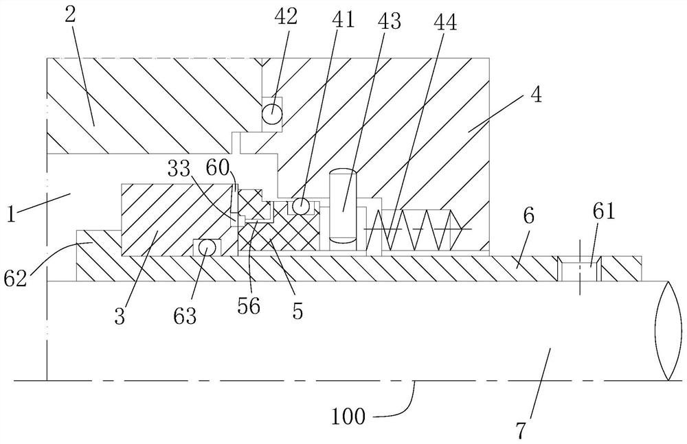
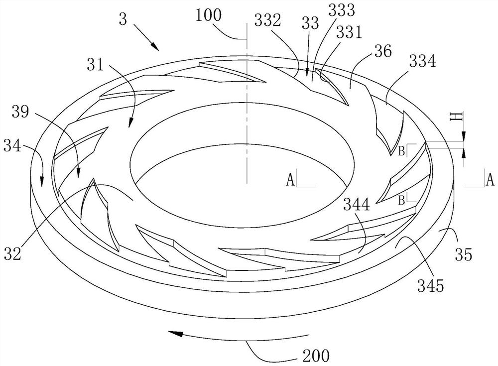
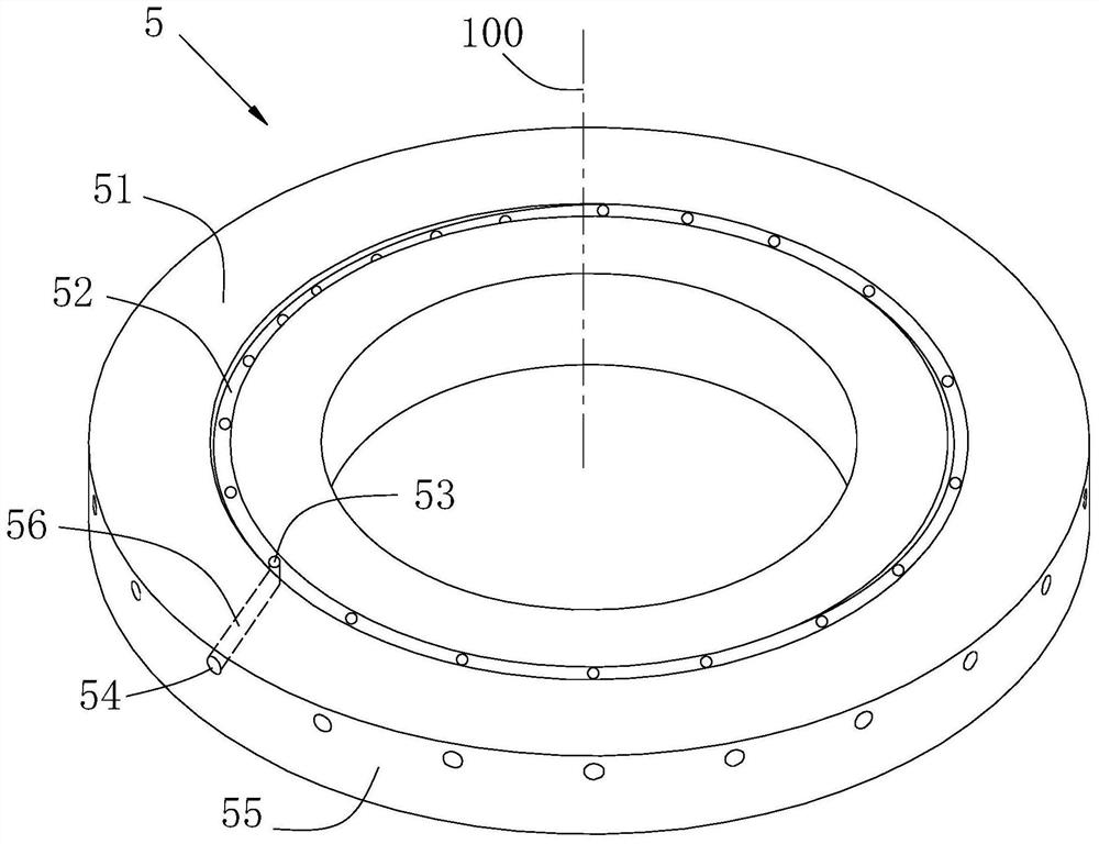
[0031] refer to figure 1 , figure 2 and image 3 , a diffuser type self-pumping fluid dynamic and static pressure mechanical seal, which is arranged between the casing 2 and the rotating shaft 7 of the rotating equipment, and includes a moving ring 3 and a static ring 5 that cooperate with each other, and the moving ring 3 and the static ring 5 is arranged coaxially along the axis 100, and a sealed chamber 1 is formed between the casing, the moving ring and the static ring.

[0032]A shaft sleeve 6 is sleeved on the rotating shaft 7 , and the shaft sleeve 6 is fixed on the rotating shaft 7 through the screw hole 61 with a set screw, and the moving ring and the static ring are both sleeved on the rotating shaft 7 . The moving ring 3 leans against the step portion 62 of the bushing 6, the static ring 5 is located outside the moving ring, the static pressure seat 4 presses the static ring 5 against the moving ring through the spring 44, and the pin 43 fixes the static ring to ...


PUM


Abstract

The invention discloses a diffusion-type self-pumped fluid dynamic and static pressure mechanical seal. The mechanical seal comprises a movable ring and a static ring which are coaxially arranged, wherein a first sealing face of the movable ring comprises a diffusion ring groove, a spiral groove area and a sealing dam from outside to inside, and a backwardly-bent spiral groove is formed in the spiral groove area; the orientation of a fluid outlet of the backwardly-bent spiral groove is opposite to the rotating direction of the movable ring; a current collecting ring groove is formed in a second sealing face of the static ring, a drainage hole channel communicating with a sealing cavity is formed in a ring body of the static ring, an inlet of the drainage hole channel is located in the peripheral face of the static ring, and an outlet of the drainage hole channel is located in the current collecting ring groove; a gap between the second sealing face and the diffusion ring groove forms an annular diffusion cavity with a radial opening; and a first bottom face of the diffusion ring groove is arranged to be a slope face or a curved face from outside to inside in the radial direction, and the slope face or the curved face is gradually close to the second sealing face from inside to outside in the radial direction. By means of the mechanical seal, large sealing end face opening force can be provided, and the requirement for zero-leakage long-period operation of a non-contact mechanical seal is met.

Description

technical field [0001] The invention relates to a pressure-diffusing self-pumping fluid dynamic and static pressure mechanical seal. Background technique [0002] Non-contact mechanical seals are widely used in centrifugal pumps, centrifugal compressors, gas turbines, steam turbines and other production equipment in petrochemical, aviation, nuclear power and other industries to ensure the seal between the rotating shaft and the housing. At present, there are mainly two forms of dry gas seal and upstream pumping mechanical seal, and the end face structure is as shown in Chinese patent ZL201020106087.8 and US patent US4290611. This type of fluid wedge dynamic pressure mechanical seal relies on the fluid entering the groove from the inner or outer diameter side, and is blocked by the seal dam at the root of the pressure groove to form a high-pressure flow field, which generates an opening force and separates the dynamic and static ring sealing interfaces, reducing Its friction...

Claims


Application Information

Patent Timeline
Patent Type & Authority Applications(China)
IPC IPC(8): F16J15/34F16J15/40
CPCF16J15/34F16J15/40
Inventor 孙见君苏徐辰马晨波於秋萍
Owner NANJING FORESTRY UNIV
Why Eureka
Try Eureka