Pump for a high-pressure cleaning device

a cleaning device and high-pressure technology, applied in the direction of pump control, positive displacement liquid engine, pump, etc., can solve problems such as pump damage, and achieve the effects of small flow loss, small flow resistance, and large flow cross section

Active Publication Date: 2012-08-23
ALFRED KARCHER GMBH & CO KG
View PDF8 Cites 5 Cited by
  • Summary
  • Abstract
  • Description
  • Claims
  • Application Information

AI Technical Summary

Benefits of technology

[0031]The suction line section extending in the joining area is preferably curved in an arc shape at least in one portion thereof. The arc-shaped curvature is advantageous, in particular, with respect to the narrow spatial conditions of the pump since, as a result, the suction line section can surround spaces for accommodating the inlet and outlet valves and for the control piston and, when required, also the pressure line. A circular arc course of the suction line section arranged in the joining area has, above all, proven to be favorable.
[0032]In one particularly preferred embodiment of the pump according to the invention, the suction line section extending in the joining area is designed as a self-contained ring. With such an embodiment, an annular space can extend in the joining area between the rear housing component and the front housing component and this forms the specified suction line section. The annular space can have a relatively large flow cross section and so the cleaning fluid to be delivered can be supplied to the at least one pump chamber with little flow resistance. The cleaning fluid can be supplied to the pump chamber with little flow loss proceeding from the pump chamber via the pressure line, the bypass line and the suction line during the circular flow operation of the pump, in particular.
[0033]The front housing component of the pump has a rear-side separating surface which is placed onto a front-side separating surface of the rear housing component with the interposition of at least one sealing element. A channel, which forms at least part of the suction line section arranged in the joining area between the two housing components, is preferably integrally formed in at least one of the separating surfaces. The channel is arranged on an outer side of at least one of the housing components and can, as a result, be produced very inexpensively.
[0034]It is favorable when a channel is integrally formed in the rear-side separating surface of the front housing component, this channel being covered by the front-side separating surface of the rear housing component and forming the suction line section arranged in the joining area between the two housing components.

Problems solved by technology

The sealing element must reliably withstand this difference in pressure even after longer operation of the pump since a leaky separation of the low pressure chamber from the high pressure chamber in the region of the control piston can lead to impairment of the pump.

Method used


Image

  • Pump for a high-pressure cleaning device
  • Pump for a high-pressure cleaning device
  • Pump for a high-pressure cleaning device

Examples


Embodiment Construction

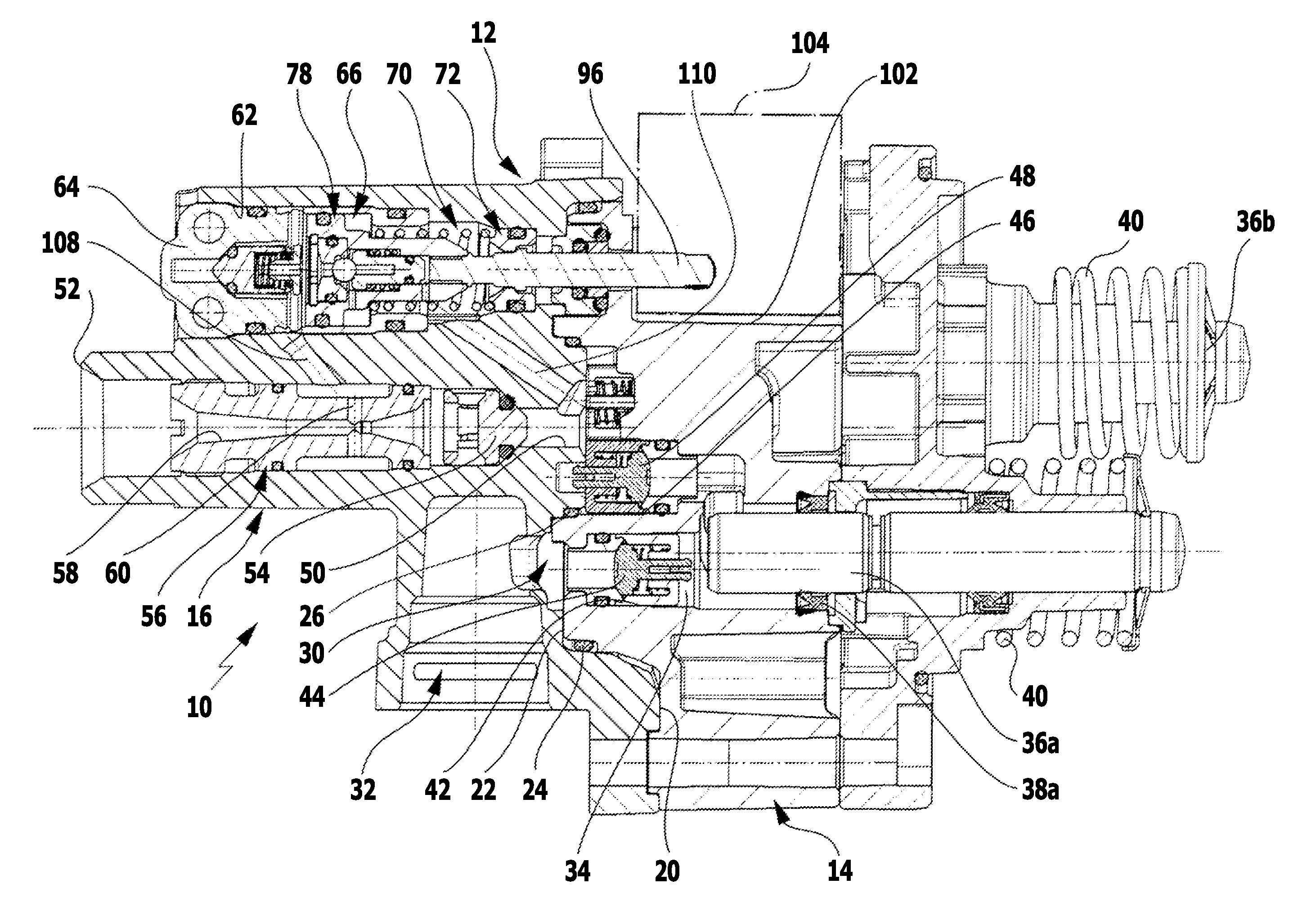
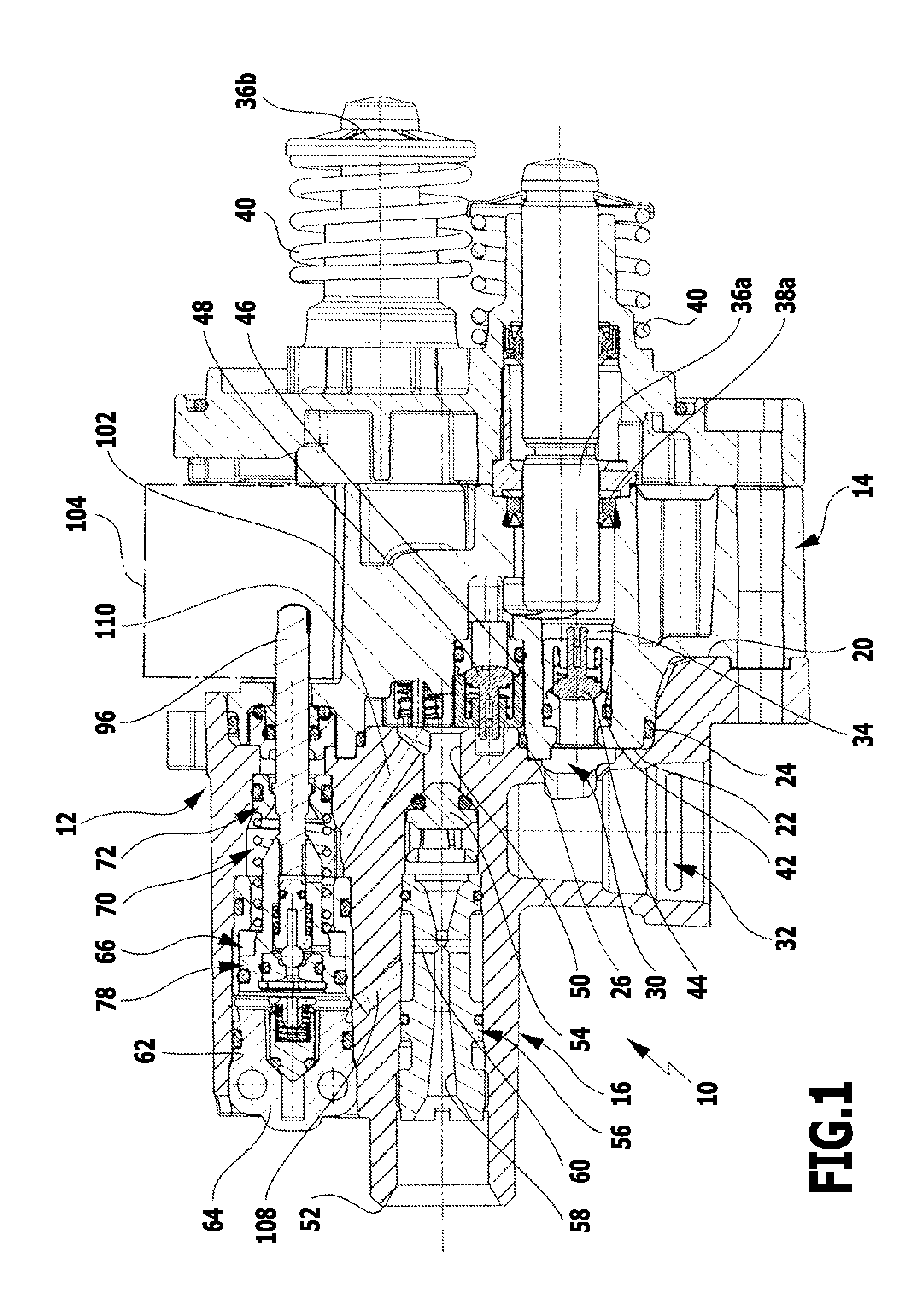
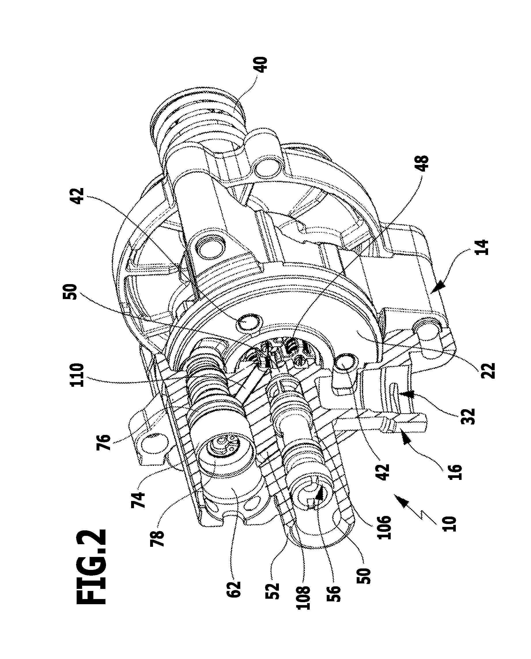
[0046]A pump 10 for a high-pressure cleaning device is illustrated schematically in the drawings. The pump 10 comprises a pump housing 12 with a rear housing component 14 and a front housing component 16. The two housing components are preferably designed in the form of aluminum pressure die castings. The front housing component 16 is provided with a rear-side separating surface 20 which is placed onto a front-side separating surface 22 of the rear housing component 14 with the interposition of an outer sealing ring 24 and an inner sealing ring 26. The two sealing rings 24 and 26 are arranged concentrically to one another on the outer and the inner edge, respectively, of an annular channel 28 which is integrally formed in the rear-side separating surface 20 of the front housing component 16. The annular channel 28 is apparent, in particular, from FIG. 3. It forms an outlet section 30 of a suction line, the inlet section 32 of which is integrally formed in the front housing component...


PUM


Abstract

A pump for a high-pressure cleaning device for delivering cleaning fluid is provided. The pump has at least one pump chamber, into which at least one piston plunges, and which is connected to a suction line via at least one inlet valve and to a pressure line via at least one outlet valve. A bypass line leads from the pressure line to the suction line. An overflow valve is arranged in the bypass line. The valve body of the overflow valve is connected to a control piston which is displaceably held in a control chamber with the interposition of a sealing element and moves the valve body into a closed or an open position as a function of the flow rate of the cleaning fluid in the pressure line. A sliding element is arranged in the control chamber and abuts sealingly on the wall of the control chamber.

Description

[0001]This application is a continuation of international application number PCT / EP2010 / 064157 filed on Sep. 24, 2010 and claims the benefit of German application number 10 2009 049 095.7 filed on Oct. 1, 2009.[0002]The present disclosure relates to the subject matter disclosed in international application number PCT / EP2010 / 064157 of Sep. 24, 2010 and German application number 10 2009 049 095.7 of Oct. 1, 2009, which are incorporated herein by reference in their entirety and for all purposes.BACKGROUND OF THE INVENTION[0003]The invention relates to a pump for a high-pressure cleaning device for delivering a cleaning fluid, comprising at least one pump chamber, into which at least one piston plunges which can be moved back and forth and which is connected to a suction line via at least one inlet valve and to a pressure line via at least one outlet valve, and comprising a bypass line which leads from the pressure line to the suction line and in which an overflow valve is arranged, the...

Claims


Application Information

Patent Timeline
Patent Type & Authority Applications(United States)
IPC IPC(8): F04B23/00
CPCF04B49/24F04B1/143
Inventor NATHAN, ROBERTERDMANN, JUERGEN
Owner ALFRED KARCHER GMBH & CO KG
Why Eureka
Try Eureka