Adjustable damping valve arrangement

a damping valve and adjustment technology, applied in the direction of shock absorbers, functional valve types, transportation and packaging, etc., can solve the problem of increasing the installation space of an outflow radially, and achieve the effect of minimizing the flow noise inside the damping valve arrangemen

Active Publication Date: 2017-04-11
ZF FRIEDRICHSHAFEN AG
View PDF14 Cites 4 Cited by
  • Summary
  • Abstract
  • Description
  • Claims
  • Application Information

AI Technical Summary

Benefits of technology

[0009]In a further advantageous embodiment, the at least one valve disk of the second supplementary valve is centered at its outer diameter with respect to the supplementary damping valve body. This increases the installation space for an outflow radially inwardly.
[0013]According to an advantageous embodiment, the second supplementary valve has an annular cover at which is supported at least one valve spring which exerts a preloading force on the at least one valve disk of the second supplementary valve. The annular cover affords the possibility of a large flow cross section between supplementary valves and the adjustable damping valve.
[0017]For purposes of a simple assembly, particularly the production of a constructional unit which can be assembled beforehand and which can accordingly be checked easily, the annular cover forms an interference fit with the supplementary valve.

Problems solved by technology

This increases the installation space for an outflow radially inwardly.

Method used


Image

  • Adjustable damping valve arrangement
  • Adjustable damping valve arrangement
  • Adjustable damping valve arrangement

Examples


Embodiment Construction

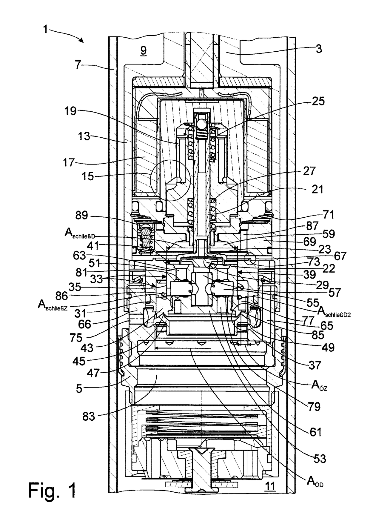
[0023]FIG. 1 shows a damping valve arrangement 1 which is fastened, e.g., to a piston rod 3 of a vibration damper, shown only partially. The damping valve arrangement 1 comprises a piston 5 which divides a cylinder 7 into a working chamber 9 on the piston rod side and a working chamber 11 remote of the piston rod, both of which working chambers 9; 11 are filled with damping medium. In this embodiment, the damping valve arrangement is fastened to the piston rod 3, but the invention is not limited to an arrangement of this kind.

[0024]An actuator 15 of optional design is arranged in an outer housing 13. Serving as actuator in this example is a magnetic coil 17 which exerts a force on an axially movable armature 19, this force being transmitted to a two-part auxiliary valve body 21 of an auxiliary valve 23. At least one valve spring—in this variant, two valve springs 25; 27 acting in opposite directions are used—preloads the auxiliary valve body 21 in the lift direction with respect to ...


PUM


Abstract

An adjustable damping valve arrangement comprises an adjustable damping valve in which flow is bidirectional, wherein a pressure-dependent supplementary valve is associated with the adjustable damping valve in series therewith for each through-flow direction, wherein each supplementary valve has at least one separate through-channel, the outlet side thereof being at least partially covered by at least one valve disk, wherein the flow path proceeding from the adjustable damping valve in flow direction is carried out through the first supplementary valve from a smaller inlet diameter to a larger outlet diameter, and the at least one valve disk carries out a peripheral lift movement, wherein the flow path through the second supplementary valve in flow direction to the adjustable damping valve is implemented from a larger inlet diameter to a smaller outlet diameter.

Description

BACKGROUND OF THE INVENTION[0001]1. Field of the Invention[0002]The present invention is directed to an adjustable damping valve and associated supplementary valves.[0003]2. Description of the Related Art[0004]An adjustable damping valve arrangement known from DE 198 22 448 A1 has a pressure-dependent supplementary damping valve disposed in series upstream of an adjustable main stage valve. The supplementary damping valve is constructed in a manner known from bottom valves which are known per se. A damping valve body has separate through-channels for both through-flow directions, which through-channels are at least partially covered at the outlet side thereof by at least one valve disk in each instance. A central fastening pin fixes the valve disks at their inner diameters.[0005]The main stage valve has a smaller diameter than the lift region of the supplementary valve. The flow path to an auxiliary valve is carried out in turn very close to a center axis of the damping valve arrang...

Claims


Application Information

Patent Timeline
Patent Type & Authority Patents(United States)
IPC IPC(8): F16K17/26F16K47/00F16F9/46
CPCF16K47/00F16F9/464F16F9/465Y10T137/8593F16F9/3481
Inventor MANGER, THOMASSCHMITT, STEFANZEISSNER, BERND
Owner ZF FRIEDRICHSHAFEN AG
Why Eureka
Try Eureka