Eureka AIR delivers breakthrough ideas for toughest innovation challenges, trusted by R&D personnel around the world.

Gear-shift device of manual transmission

a gear shifter and manual transmission technology, applied in the direction of mechanical control devices, manual control with single controlling member, instruments, etc., can solve the problems of limiting the increase of leverage that is effected, the stroke of the change lever, and the inability to achieve the desired effect, increase the installation space, and reduce the effect of the operation for

Active Publication Date: 2009-10-06
HONDA MOTOR CO LTD
View PDF10 Cites 7 Cited by
  • Summary
  • Abstract
  • Description
  • Claims
  • Application Information

AI Technical Summary

Benefits of technology

[0006]It is an object of the present invention to provide a gear-shifting device for a manual transmission, which device has a variable leverage to improve the maneuverability of the change-lever, which has an appropriate and secure stroke for a smooth shift operation.
[0011]Therefore, in the initial stage of the operation of the change-lever, the leverage is set at a relatively large value to make a relatively small operational force applied by the driver act on the shift fork as a large force to ensure the synchronization of the synchromesh mechanism. On the other hand, this large force acting on the shift fork is no longer necessary after the synchronization, so the leverage is designed to change to a lower value, halfway through the shift operation executed by the driver. In this way, the rate of the displacement of the shift fork to that of the change-lever is increased, halfway through the operation, for the complete actuation of the shift fork. Therefore, the stroke of the change-lever for the completion of the shift operation in the gear-shifting device according to the present invention is still made equal to that of a prior-art gear-shifting device, so the present invention does not require an increase in the installation space of the change-lever especially in the interior of the vehicle.
[0012]In the above described gear-shifting device, the point where the leverage changes from a larger value to a smaller value during the shift operation can be set to come after the synchronization of the synchromesh mechanism. In this way, the rate of the displacement of the shift fork to that of the change-lever is increased after the synchronization to quickly bring the gear into engagement. As a result, so-called “two-step engaging load”, which is a reaction generated at the time of the gear meshing in the synchromesh mechanism and which is uncomfortable to the driver who is operating the change-lever, is reduced in frequency and in magnitude.

Problems solved by technology

However, there is a limit to the increase of the leverage that is effected by increasing the stroke of the change-lever because the installation space of the change-lever in the interior of a vehicle is limited.
Also, it is not desirable from the point of view of the driver's maneuverability of the change-lever.
This may result in an impairment to the secure clutching operation.
On the other hand, the increasing of the synchronization capacity results in an increase in the number of the parts constituting the transmission and can lead to an increase in the manufacturing cost of the transmission.

Method used


Image

  • Gear-shift device of manual transmission
  • Gear-shift device of manual transmission
  • Gear-shift device of manual transmission

Examples


Embodiment Construction

[0020]Now, a preferred embodiment of gear-shifting device for a manual transmission according to the present invention is described in reference to FIGS. 1˜7.

[0021]This manual transmission, when its Low, 2nd˜5th or Reverse clutch is selectively engaged, transmits the driving force of an engine selectively through a gear train with a different speed change ratio. For a gear shift, the driver manually operates the change-lever L provided at the driver seat. The following is a description of the mechanism to achieve a gear shift.

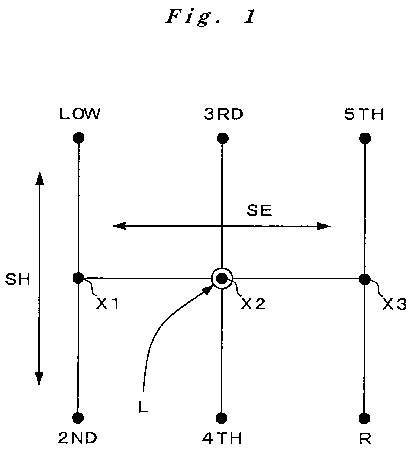
[0022]The change-lever L, which is used to select one of the 1st˜5th speed change ratios and reverse ratio (hereinafter referred to as “R speed”), is operated in the patterns shown in FIG. 1. If the change-lever L is operated in the direction indicated by SE in the drawing, then it can be positioned at one of the three selecting positions: 1st-2nd speed selecting position X1, 3rd-4th speed selecting position X2, and 5th-R speed selecting position X3. Then, whil...


PUM


Abstract

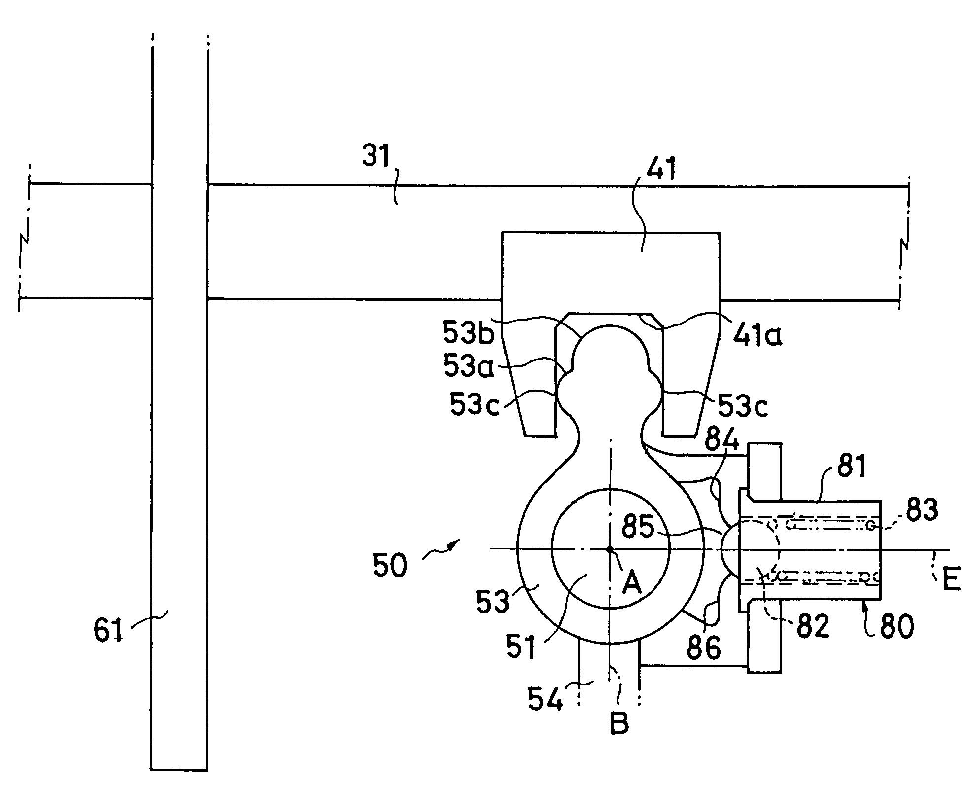
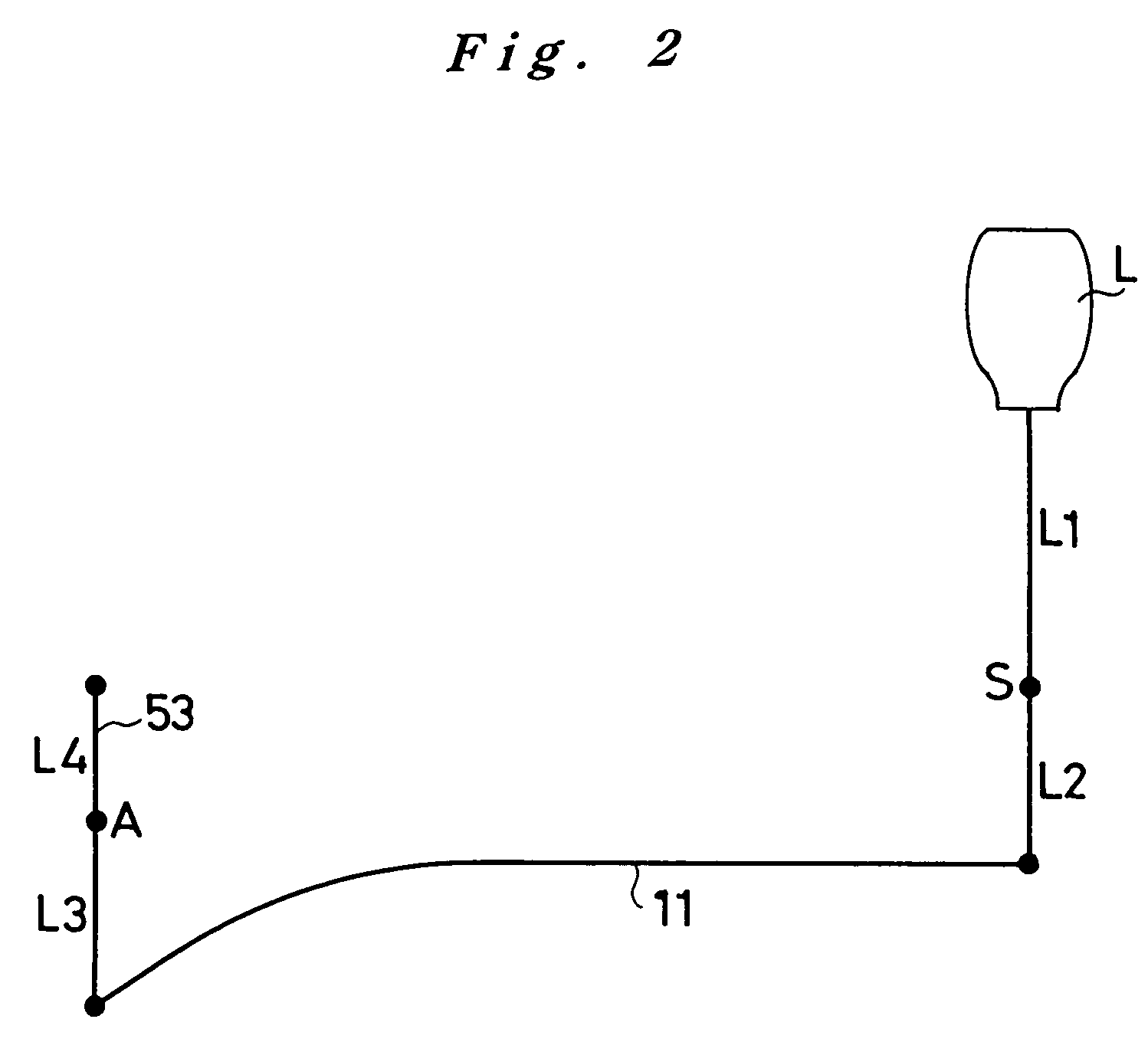
A gear-shifting device for a manual transmission, in which the operational force applied at the change-lever L in the shift operation is transmitted selectively to actuate a synchro-sleeve for a gear shift, comprises a shift arm 53, which is rotatable in correspondence to the shift operation of the change-lever L, and a 1st-2nd speed shift piece 41, which is in contact with the shift arm 53 and is capable of shifting in response to the rotation of the shift arm 53. In the gear-shifting device, the shift arm 53 has heteromorphous cams at its contacting part, which is in contact with the 1st-2nd speed shift piece 41, and the heteromorphous cams are designed in a compound arc figure, which comprises a plurality of combined arcs having different curvature radii. As a result, while the shift arm 53 is rotating in correspondence to the shift operation, the distance between the contacting part and the rotational axis of the shift arm 53 varies to change the leverage effective between the change-lever L and the contacting part.

Description

FIELD OF THE INVENTION[0001]The present invention relates generally to a gear-shifting device for a manual transmission, which device actuates a shift fork to bring into engagement selectively a clutch that establishes a power transmission through a corresponding gear train in gear-shifting control. The present invention relates particularly to a gear-shifting device in which a force applied in operating the change-lever manually is transmitted to a shift fork to bring a corresponding clutch into engagement in the manual transmission.BACKGROUND OF THE INVENTION[0002]Generally, in a manual transmission (manual gear-shift transmission), when the driver operates the change-lever manually, the force applied by the driver in the operation is transmitted through a gear-shifting device to a shift fork, so that the shift fork sets a corresponding clutch (for example, a synchromesh mechanism) into engagement, establishing a desired speed change ratio for the transmission. Such clutches are a...

Claims


Application Information

Patent Timeline
Patent Type & Authority Patents(United States)
IPC IPC(8): F16H59/04F16H61/32F16H63/32F16H63/20F16H63/30F16H63/38
CPCF16H63/20F16H63/3016F16H63/38Y10T74/20183Y10T74/20177Y10T74/20018F16H2063/3083
Inventor MATSUDA, KENJI
Owner HONDA MOTOR CO LTD
Why Eureka
Eureka Blog
Learn More