Optical measuring method and measuring apparatus for external dimension

a technology for measuring equipment and measuring methods, applied in the direction of measuring devices, caliper-like sensors, instruments, etc., can solve the problems of increasing the cost of devices, and achieve the effect of preventing the increase of the cost of the apparatus and expanding the installation spa

Inactive Publication Date: 2017-06-15
MITUTOYO CORP
View PDF9 Cites 7 Cited by
  • Summary
  • Abstract
  • Description
  • Claims
  • Application Information

AI Technical Summary

Benefits of technology

[0009]The present invention provides an optical measuring method and measuring apparatus for an external dimension which allow simultaneous measurements in a plurality of directions and can prevent a cost increase of a device and an expansion of an installation space.
[0011]In the present invention, by a simple configuration with a reflector added to a paired light emitter and photoreceiver, the simultaneous measurement of the external dimension in the main direction and the sub direction of the measured object can be achieved. At this point, the light emitter and the photoreceiver in the existing laser scan micrometer or the image sensor micrometer can be applied for the paired light emitter and photoreceiver. In addition, an existing reflection mirror for optical measurement can be used for the reflector. As described above, according to the present invention, even with a single light emitter and photoreceiver system, simultaneous measurement in a plurality of directions can be achieved and an increase in the cost of the device and an expansion of the installation space can be prevented.
[0014]The present invention enables simultaneous measurement in a plurality of directions and can provide the optical measuring method and the measuring apparatus for the external dimension capable of preventing increased cost in the apparatus and the expansion of the installation space.

Problems solved by technology

However, when a plurality of sets of light emitters and photoreceivers are installed, a cost of a device may increase and a space to install all the sets may expand as well.

Method used


Image

  • Optical measuring method and measuring apparatus for external dimension
  • Optical measuring method and measuring apparatus for external dimension
  • Optical measuring method and measuring apparatus for external dimension

Examples


first embodiment

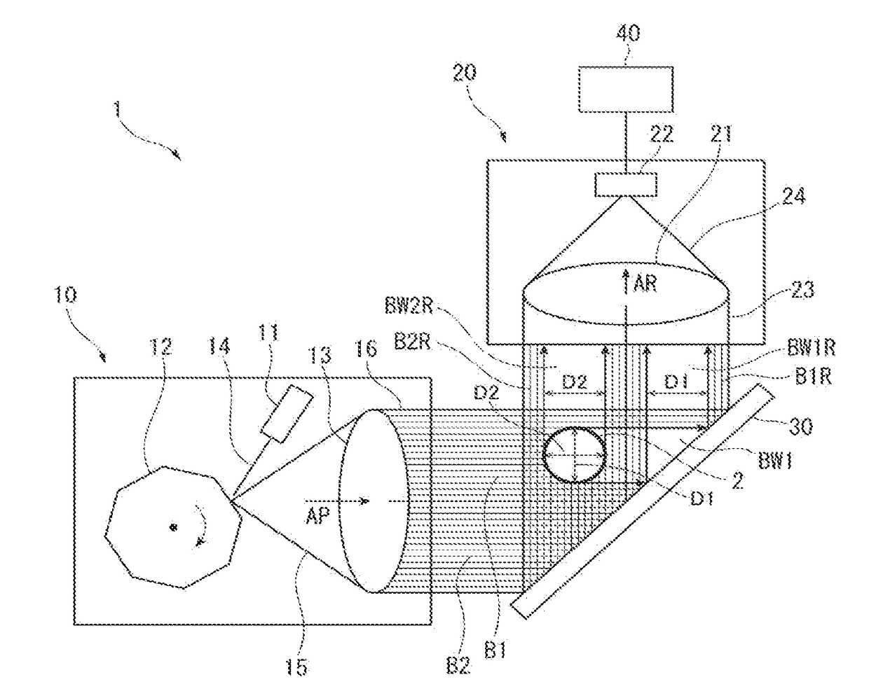
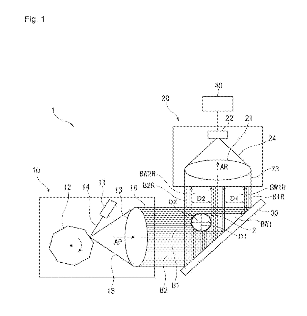
[0023]FIGS. 1 and 2 illustrate a first embodiment according to the present invention. In FIG. 1, a measuring apparatus 1 is an optical measuring apparatus for an external dimension based on the present invention and measures an external dimension of a measured object 2. In the present embodiment, the measured object 2 is a bar shaped object having a circular cross-section and extends in a direction perpendicular to a paper surface of FIG. 1. In the present embodiment, the external dimensions (outer diameters D1 and D2) are measured simultaneously in two directions of the measured object 2 using the measuring apparatus 1. The measuring apparatus 1 includes a light emitter 10, a photoreceiver 20, and a reflector 30.

[0024]The light emitter 10 includes a laser light source 11, polygonal mirror 12, and a collimator lens 13. In the light emitter 10, beam-shaped laser light 14 from the laser light source 11 is reflected by the polygonal mirror 12. Reflection light 15 is emitted through the...

second embodiment

[0036]FIG. 3 illustrates a second embodiment according to the present invention. A measuring apparatus 1A of the second embodiment includes the light emitter 10, the photoreceiver 20, and the control apparatus 40 similar to the measuring apparatus 1 in the first embodiment described above. However, two reflection mirrors 31 and 32 are used as the reflector and three regions are assigned to the measuring light beam 16 and the reflection light beam 23.

[0037]The two reflection mirrors 31 and 32 are arranged mutually forming a 60 degree angle. The measuring light beam 16 from the light emitter 10 is arranged parallel to a surface of the second reflection mirror 32 and strikes the first reflection mirror 31 at a 60 degree angle. The light beam reflected by the first reflection mirror 31 is sent to the second reflection mirror 32 and is further reflected to form the reflection light beam 23. The reflection light beam 23 proceeds parallel to the surface of the first reflection mirror 31 an...

third embodiment

[0043]FIG. 4 illustrates a third embodiment according to the present invention. A measuring apparatus 1B of the third embodiment includes the light emitter 10, the photoreceiver 20, and the control apparatus 40 similar to the measuring apparatus 1 in the first embodiment described above. Further, similar to the second embodiment, the two reflection mirrors 31 and 32 are used as the reflector and three regions are assigned to the measuring light beam 16 and the reflection light beam 23.

[0044]The difference with the second embodiment mentioned above is the place where the measured object 2 is arranged. In the present embodiment, the measured object 2 is placed on the optical path of the second measuring light beam B2 and in a measuring region on the optical paths of the first reflection light beam B1R and the third re-reflected light beam B3RR. The first reflection light beam B1R is fired in the first direction A1 at the measured object 2 placed in the measuring region, which forms th...


PUM


Abstract

A light emitter and a reflector are placed such that an optical axis of a measuring light beam and an optical axis of a reflection light beam intersect, and further the measuring light beam and the reflection light beam are formed inside the same virtual measuring plane; a first measuring light beam and a second measuring light beam are defined in the measuring light beam, a first and second reflection light beam are defined in the reflection light beam, a measured object is placed in a measuring region on a measuring plane where the first and second measuring light beams overlap, an external diameter of the measured object in a first direction is measured from a shadow appearing in the first reflection light beam and an external diameter of the measured object in a second direction is measured from a shadow appearing in the second reflection light beam.

Description

CROSS-REFERENCE TO RELATED APPLICATIONS[0001]The present application claims priority under 35 U.S.C. §119 of Japanese Application No. 2015-244239, filed on Dec. 15, 2015, the disclosure of which is expressly incorporated by reference herein in its entirety.BACKGROUND OF THE INVENTION[0002]1. Field of the Invention[0003]The present invention relates to an optical measuring method and measuring apparatus for an external dimension, and relates to a method and an apparatus measuring outer diameters of a measured object in a plurality of directions simultaneously.[0004]2. Description of Related Art[0005]Optical measuring apparatuses are used in order to conduct non-contact measurement of an external dimension of a measured object (such as an outer diameter of a cylindrical object). For example, a laser scan micrometer, image sensor micrometer, or light-section type 2D (two dimensional) shape measuring sensor is used. These apparatuses detect the outer diameter of the measured object from...

Claims


Application Information

Patent Timeline
Patent Type & Authority Applications(United States)
IPC IPC(8): G01B11/02
CPCG01B11/028G01B11/02G01B11/08G01B2210/46G01B11/2433
Inventor MIKI, YUTAKA
Owner MITUTOYO CORP
Why Eureka
Try Eureka