Image forming apparatus

Active Publication Date: 2017-06-08
CANON KK
View PDF1 Cites 5 Cited by
  • Summary
  • Abstract
  • Description
  • Claims
  • Application Information

AI Technical Summary

Benefits of technology

[0007]It is a feature of the present invention to cool heat generating components in an im

Problems solved by technology

Consequently, the heat generating components in the image forming apparatus are not

Method used


Image

  • Image forming apparatus
  • Image forming apparatus
  • Image forming apparatus

Examples


embodiment

[0017]An embodiment of the present invention will be illustrated below by way of example with reference to the drawings. However, the sizes, materials, shapes, and relative locations of the components described in the following embodiment are to be changed as required depending on the configuration and conditions of the apparatus to which the present invention is applied, and the scope of the present invention is not limited to the embodiment described below.

[0018]

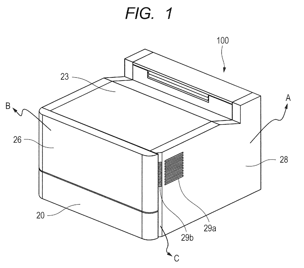
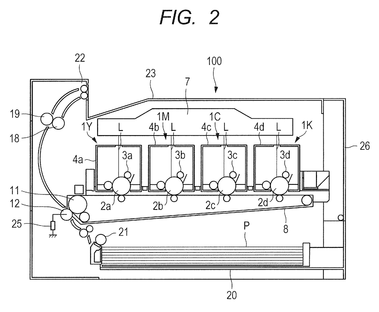
[0019]FIG. 1 is an external perspective view of an image forming apparatus 100 according to an embodiment. Also, FIG. 2 is a schematic sectional view of the image forming apparatus 100 according to the embodiment. In the embodiment, the image forming apparatus 100 is an electrophotographic tandem laser printer. A laser scanner 7, photosensitive drums2a to 2d, developing devices 4a to 4d, an intermediate transfer belt 8, a fixing film 18, a pressure roller 19, a feeding tray 20 and a feeding roller 21 are installed in the i...


PUM


Abstract

The image forming apparatus includes an open/close cover, a side cover, and a fan configured to take in ambient air through a vent hole, and generate airflow to cool an inside of the image forming apparatus, wherein the side cover includes an outside surface C, at least part of which faces the open/close cover, and a vent hole is provided in the outside surface C.

Description

BACKGROUND OF THE INVENTION[0001]Field of the Invention[0002]The present invention relates to an image forming apparatus adapted to cool heat generating components in the image forming apparatus.[0003]Description of the Related Art[0004]Conventionally, as disclosed in Japanese Patent Application Laid-Open Nos. H11-084989 and 2003-076253, an image forming apparatus is provided with an air blowing unit adapted to cool heat generating components such as a process cartridge and power supply in the image forming apparatus by sending air into the image forming apparatus from outside the image forming apparatus. Such an image forming apparatus has a vent hole provided in a side face of the image forming apparatus in order for air to enter the image forming apparatus from outside the image forming apparatus. Also, a fan is provided in the neighborhood of the vent hole in the image forming apparatus to send air into the image forming apparatus from outside the image forming apparatus.[0005]T...

Claims


Application Information

Patent Timeline
IPC IPC(8): G03G21/20
CPCG03G21/206G03G21/1633G03G2215/0132G03G2221/1684
Inventor IMANARI, HIROSHITAKAHASHI, SATORU
Owner CANON KK
Why Eureka
Try Eureka