Ventilation unit for a die casting device

A kind of exhaust device and equipment technology, which is applied in the direction of casting molding equipment, metal processing equipment, casting mold, etc., and can solve the problem of insufficient molding cavity

Inactive Publication Date: 2010-11-10
ELECTRONICS GMBH VERTRIEB ELEKTRONISCHER GERATE
View PDF1 Cites 4 Cited by
  • Summary
  • Abstract
  • Description
  • Claims
  • Application Information

AI Technical Summary

Problems solved by technology

It has been shown that in many cases, despite the availability of powerful gas suction devices, the forming cavities can only be degassed to an insufficient degree

Method used


Image

  • Ventilation unit for a die casting device
  • Ventilation unit for a die casting device
  • Ventilation unit for a die casting device

Examples


Embodiment Construction

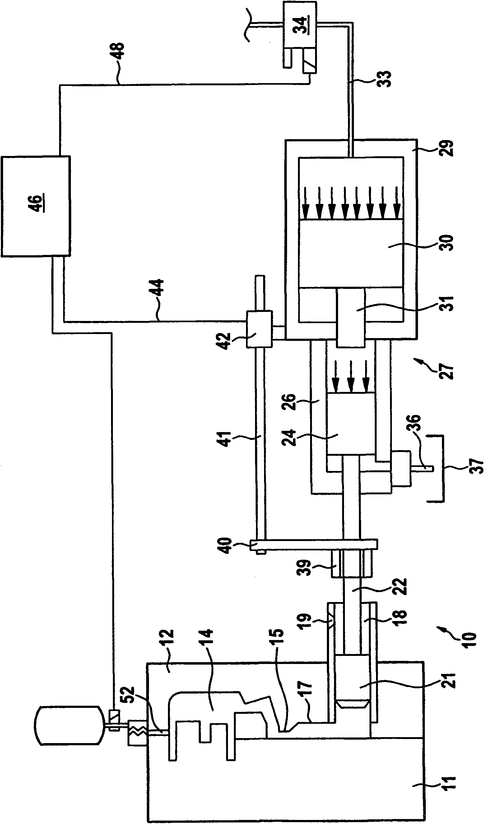
[0028] exist figure 1 A die-casting device 10 according to the invention is schematically shown in FIG. A mold closing unit not shown in the figures cooperates. The mold closing unit comprises movable jaws and fixed jaws, which are not shown in the figures for a better overview, and one of the two mold halves 11 , 12 is advantageously held in each case on these splints. With the aid of this mold closing unit, a predetermined clamping force can be applied to the two mold halves 11 , 12 . The two mold halves 11, 12 form between each other a forming cavity 14 which has the shape of the casting to be cast, into which the casting material (such as a metal melt, preferably liquid aluminum or Magnesium material) is pressed into the molding cavity 14. For this purpose, the forming cavity 14 has an access opening, which is commonly referred to as a "cutting surface (Anschnitt)" and is located at figure 1 are marked with reference numeral 15. The cut surface 15 is connected via an...


PUM


Abstract

The invention relates to a ventilation unit for a die casting device, comprising a mold cavity that can be filled with liquid casting material and a gas suction device for suctioning the mold cavity, said suction device being connected to the mold cavity, wherein the ventilation unit comprises a flow labyrinth, the input of which can be connected to the mold cavity and the output of which can be connected to the gas suction device. In order to refine the ventilation unit such that it enables improved evacuation of the mold cavity, without the risk of liquid casting material exiting the ventilation device, according to the invention it is proposed that the flow cross-section of the flow labyrinth be variable. In addition, a die casting device comprising such a ventilation unit is proposed.

Description

technical field [0001] The invention relates to an exhaust device for a die-casting plant having a molding cavity that can be filled with liquid casting material and a gas suction device connected to the molding cavity for degassing the molding cavity. The cavity is pumped, wherein the exhaust device comprises a flow labyrinth whose input can be connected to the forming cavity and whose output can be connected to the gas suction device. [0002] Furthermore, the invention relates to an injection molding installation with such a venting device. Background technique [0003] A die-casting device is known, for example, from DE 20 2005 019 288 U1. Die-casting devices have a forming cavity into which a liquid casting material, for example an aluminum or magnesium melt, can be pressed. In order to avoid air bubbles trapped in the casting material, which is initially liquid and then hardens within a short time, which could impair the quality of the cast parts produced, the moldin...

Claims


Application Information

Patent Timeline
Patent Type & Authority Applications(China)
IPC IPC(8): B22D17/14B22C9/06B29C45/34
CPCB22D17/145B22C9/067
Inventor 约尔格·高尔曼
Owner ELECTRONICS GMBH VERTRIEB ELEKTRONISCHER GERATE
Why Eureka
Try Eureka