Liquid crystal display device

A technology of liquid crystal display device and display panel, which is applied in nonlinear optics, instruments, optics, etc., and can solve the problem that the liquid crystal display device cannot clearly see the display panel, etc.

Inactive Publication Date: 2007-05-09
INNOCOM TECH SHENZHEN +1
View PDF0 Cites 2 Cited by
  • Summary
  • Abstract
  • Description
  • Claims
  • Application Information

AI Technical Summary

Problems solved by technology

[0005] In order to solve the problem that the liquid crystal display device in the prior art cannot make people far away and in different directions clearly see the content displayed on the display panel, it is necessary to provide a Liquid crystal display device that sees what is displayed on the display panel

Method used


Image

  • Liquid crystal display device
  • Liquid crystal display device
  • Liquid crystal display device

Examples


Embodiment Construction

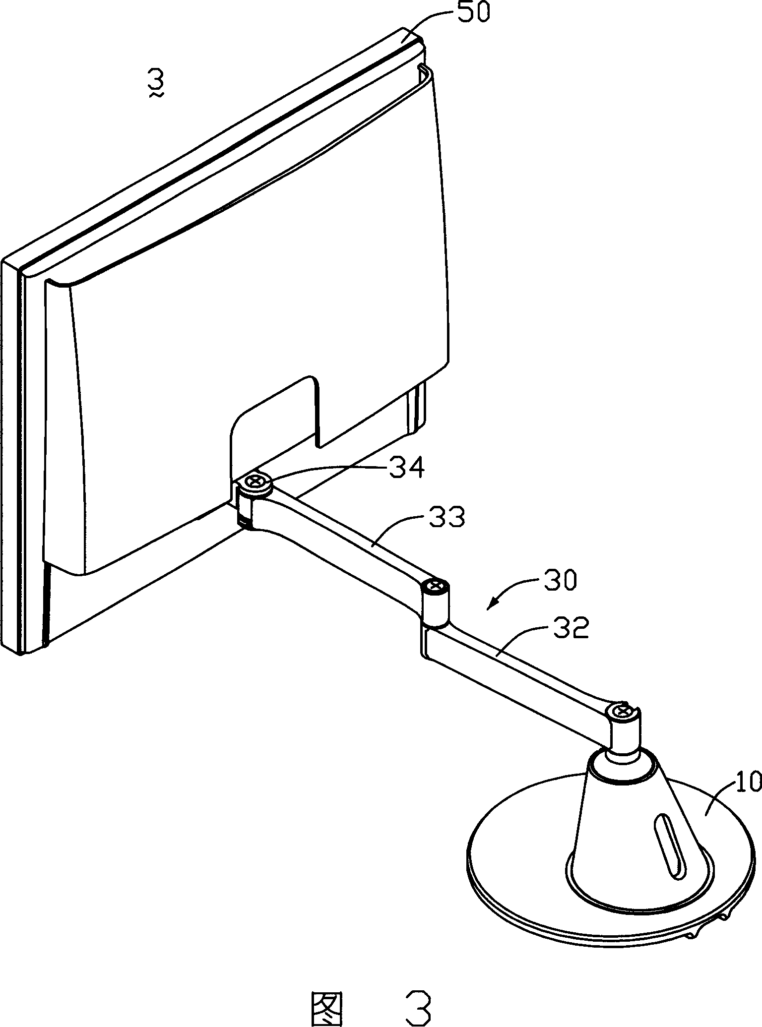
[0015] Referring to FIG. 3 , it is a schematic diagram of a preferred embodiment of the liquid crystal display device of the present invention. The liquid crystal display device 3 includes a support structure 10 , a connecting mechanism 30 and a display panel 50 . The supporting structure 10 is connected to one end of the connecting mechanism 30 to hold the connecting mechanism 30 , and the other end of the connecting mechanism 30 is connected to the display panel 50 to support the display panel 50 . The connecting mechanism 30 includes a first connecting rod 32 , a second connecting rod 33 and a pivot portion 34 which are sequentially connected. The connecting mechanism 30 can push the display panel 50 to a position farther away from the supporting structure 10 .

[0016] Referring to FIG. 4 , which is an exploded perspective view of the liquid crystal display device shown in FIG. 3 , the support structure 10 includes a disc-shaped base 11 and a bracket 15 . The disc-shaped b...


PUM


Abstract

A liquid crystal display device consists of a display face plate; a connection mechanism including a pin-joint unit being connected separately to said face plate and link unit, and a link unit; as well as a support structure being connected to said link unit for making personnel at different positions view content displayed on face plate clearly.

Description

【Technical field】 [0001] The invention relates to a liquid crystal display device. 【Background technique】 [0002] With the advancement of electronic technology, especially the prevalence of portable electronic products in daily life, people's demand for thin, light, small and low power consumption displays is increasing day by day. Due to the advantages of low power consumption, low heat generation, light weight, no radiation, and soft pictures, liquid crystal displays have a tendency to gradually replace traditional cathode ray tube displays. [0003] A kind of liquid crystal display of prior art is shown in Figure 1 and Figure 2, and this liquid crystal display 9 comprises a base 91, a support 92 and a display panel 93, and this support 92 is arranged on the base 91 in the mode of rotation, The display panel 93 is pivotally fixed on the bracket 92 via a pivot 94 (or hinge). [0004] When the liquid crystal display 9 is placed on a support plane (such as a desktop), the ...

Claims


Application Information

Patent Timeline
Patent Type & Authority Applications(China)
IPC IPC(8): G02F1/1333
Inventor 黄泽民陈永祥姜启文朱建同梁云龙陈俊建
Owner INNOCOM TECH SHENZHEN
Why Eureka
Try Eureka