Control circuit and control method for switch power supply, and switch power supply

a control circuit and power supply technology, applied in the field of power electronics, can solve the problems of limited input voltage and output voltage range of the switch power supply, and achieve the effects of wide input and output voltage range, improved system stability, and improved maximum value of duty ratio dmax

Active Publication Date: 2019-02-26
JOULWATT TECH INC LTD
View PDF4 Cites 2 Cited by
  • Summary
  • Abstract
  • Description
  • Claims
  • Application Information

AI Technical Summary

Benefits of technology

[0027]The control circuit of the switch power supply of the present invention uses dynamic control of the reference period to compensate the change of the event parameter of switch signal, thereby realizing the wide input and output voltage range and improving the system stability.
[0028]In one embodiment, in constant on time control mode of the switch power supply, if the off time is less than the first threshold, the reference period is extended. The first threshold corresponds to the minimum off time. The reference period is dynamically adjusted by the off time of the switch signal so that the off time is always greater than the minimum off time. Therefore, the control method compensates for the change of the off time of the switch signal by dynamically controlling the reference period, which can further improve the maximum value of duty ratio Dmax to realize a wide input and output voltage range.
[0029]In one embodiment, in constant on time control mode of the switch power supply, if the off time is greater than or equal to the first threshold, the reference period decreases. The reference period is dynamically adjusted by the off time of the switch signal. When the off time of the switch signal is greater than the minimum off time, the control circuit further increases the frequency of the switch signal, thus the system efficiency is improved and the generation of the audio noise is avoided.
[0030]In one embodiment, in constant off time control mode of the switch power supply, if the on time is less than the second threshold, the reference period is extended. The second threshold corresponds to the minimum on time. The reference period is dynamically adjusted by the on time of the switch signal so that the on time is always greater than the minimum on time. Therefore, the control method compensates the change of the on time of the switch signal by dynamically controlling the reference period, which can further reduce the minimum value of duty ratio Dmin to realize a wide input and output voltage range.
[0031]In one embodiment, in constant off time control mode of the switch power supply, if the on time is greater than or equal to the second threshold, the reference period decreases. The reference period is dynamically adjusted by the on time of the switch signal. When the on time of the switch signal is greater than the minimum on time, the control circuit further increases the frequency of the switch signal, thus the system efficiency is improved and the generation of the audio noise is avoided.

Problems solved by technology

So, the range of the input voltage and the output voltage of the switch power supply is limited.

Method used


Image

  • Control circuit and control method for switch power supply, and switch power supply
  • Control circuit and control method for switch power supply, and switch power supply
  • Control circuit and control method for switch power supply, and switch power supply

Examples


first embodiment

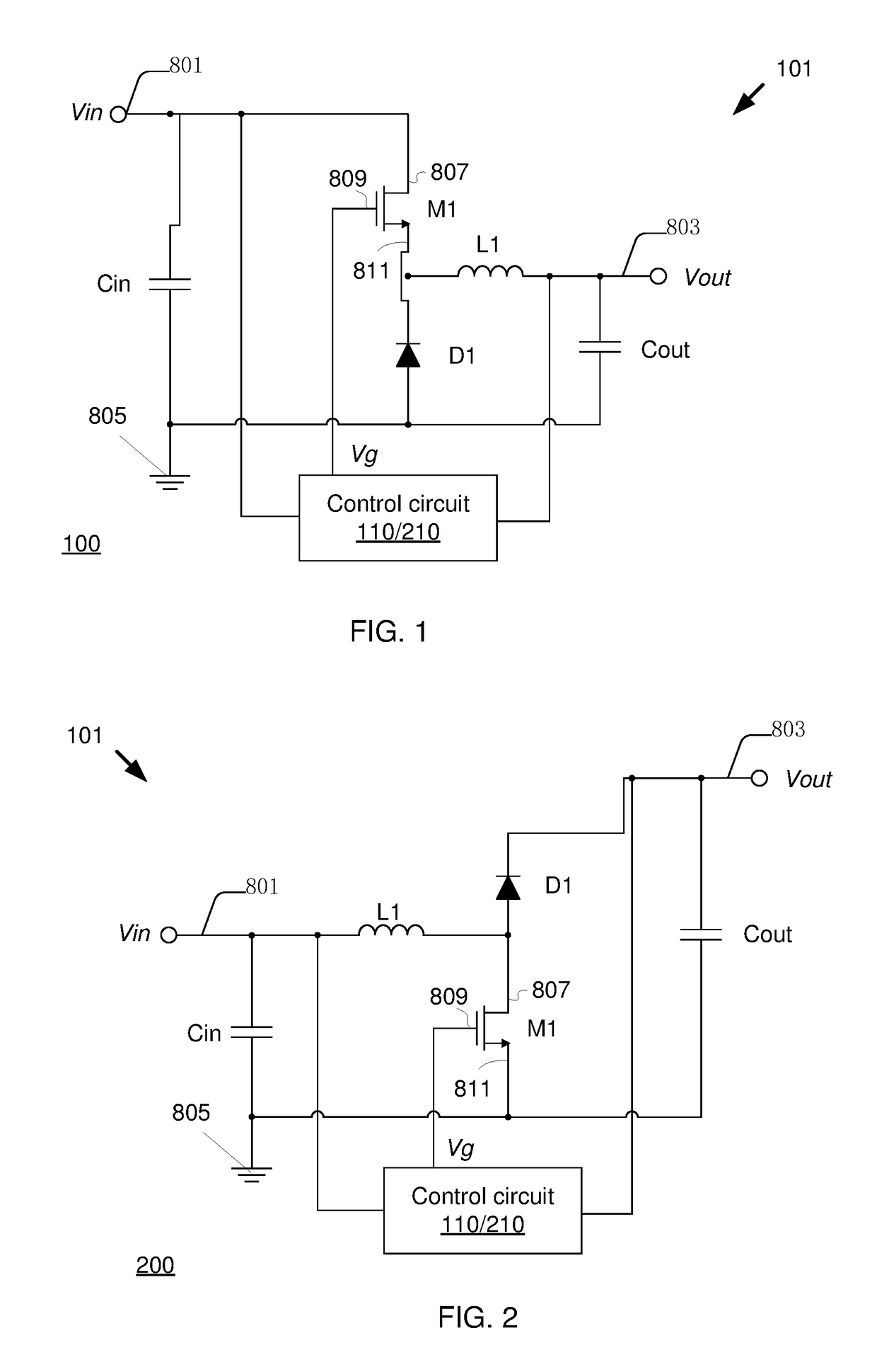
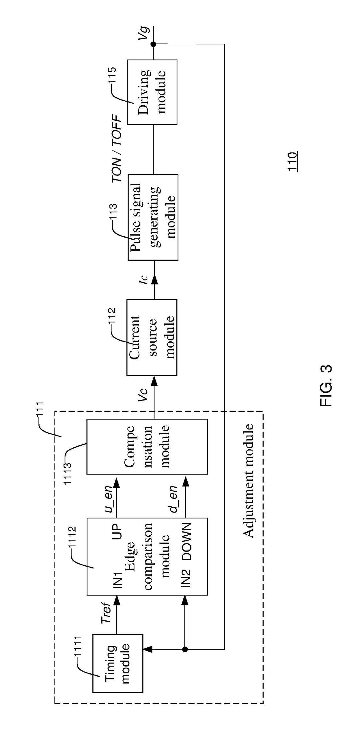
[0114]FIG. 7 is a schematic block diagram of a control circuit 210 of the switch power supplies 100 / 200 according to the disclosure. As shown in FIG. 7, the control circuit 210 includes an adjustment module 211, a current source module 212, a pulse signal generating module 213, a time measurement module 214 and a drive module 215. The adjustment module 211 generates the control voltage Vc based on the switch signal Vg. The current source module 212 produces the charging current Ic according to the control voltage Vc. In constant on time control mode, the pulse signal generating module 213 generates the switch turn-on signal TON in accordance with the charging current Ic. The drive module 215 produces the switch signal Vg based on the switch turn-on signal TON.

[0115]The structure and function of the current source module 212, the pulse signal generating module 213 and drive module 215 of the switch power supply control circuit in this embodiment are the same as the current source mod...

second embodiment

[0142]FIG. 10 is a flow chart of a constant on time control method of the switch power supply according to the disclosure. In this embodiment, the control method is realized by using the control circuit 210 shown in FIG. 7 and the timing module 2111 shown in FIG. 8 after the switch power supply 100 / 200 is powered on. The control method performs some but not all of the functions of the control circuit 210.

[0143]In step S101, the off time Tf of the switch signal Vg is detected.

[0144]In step S102, the control circuit 210 decides whether the off time Tf of the switch signal is smaller than the first threshold Tth1. For example, the first threshold Tth1 corresponds to the minimum off time Tf_min of the system. If the off time Tf of the switch signal Vg is smaller than the first threshold Tth1, step S105 is executed, and if the off time Tf of the switch signal Vg is greater than or equal to the first threshold Tth1, step S104 is executed.

[0145]In step S104, the current of the current sour...

third embodiment

[0148]FIG. 11 is a flow chart of a constant on time control method of the switch power supply according to the disclosure. In this embodiment, the control method is realized by using the control circuit 210 shown in FIG. 7 and the timing module 2111 shown in FIG. 8 after the switch power supply 100 / 200 is powered on. The control method performs some but not all of the functions of the control circuit 210.

[0149]The steps S201, S202, S205 and S206 of the switch power supply control method in this embodiment are the same as the corresponding steps S101, S102, S105 and S106 of control method shown in FIG. 10. The difference of the two is described below.

[0150]In step S202, the control circuit 210 decides whether the off time Tf of the switch signal is smaller than the first threshold Tth1. For example, the first threshold Tth1 corresponds to the minimum off time Tf_min of the system. If the off time Tf of the switch signal Vg is smaller than the first threshold Tth1, step S205 is execut...


PUM


Abstract

For controlling a switch power supply, an adjustment module produces a first control voltage by comparing a period of a switch signal with a reference period. A current source module generates a first charging current according to the first control voltage. A pulse signal generating module converts the first charging current into an on time signal or off time signal of a switch transistor. A driving module produces the switch signal according to the on time or off time signal of the switching transistor, so as to control the turn on and turn off signal of a switching transistor. A time measurement module obtains a time parameter according to the switch signal, and generates a periodic adjustment signal according to the time parameter. The adjustment module adjusts the reference period according to the periodic adjustment signal to adjust the period of the switch signal.

Description

CROSS-REFERENCE TO RELATED APPLICATION[0001]This application claims the benefit of Chinese Patent Application No. 201610907264.4, filed on Oct. 19, 2016, which is incorporated herein by reference in its entirety.FIELD[0002]The present disclosure relates to the field of power electronics, and more particularly, to a control circuit and a control method for a switch power supply, and a switch power supply.BACKGROUND[0003]The switch power supply uses the switch signals to control the turn-on and turn-off of the switching transistors, and maintains the stable output of the power circuit through the charging and discharging of the energy storage element. In the switch power supply, the control circuit generates switch signals to control the turn-on and turn-off of the switching transistors. The ratio of the on time of the switching transistor to the whole switching period is called duty period. There is a specific relationship between and among the input voltage, the output voltage and t...

Claims


Application Information

Patent Timeline
Patent Type & Authority Patents(United States)
IPC IPC(8): H02M3/158H02M3/156H02J3/38H02J3/44H02M3/335H02M7/48H03K17/06H03K17/56
CPCH02M3/1582H02J3/38H02J3/44H03K17/56H02M3/335H02M7/48H03K17/063H02M3/1563H02M1/44H02M3/158
Inventor CHAN, SIOPANGWONG, PITLEONGREN, YUANCHENGZHOU, XUNWEI
Owner JOULWATT TECH INC LTD
Why Eureka
Try Eureka