
Haptic reactive electrical switch

a technology of electrical switches and reactive electrical switches, applied in the field of electrical switches, can solve the problems of increased size of electrical switches incorporating the means of vibration feedback, weak vibration force transmitted to the user's finger, and increased size of electrical switches

Active Publication Date: 2022-10-04
ALPS ELECTRIC KOREA
View PDF3 Cites 0 Cited by
  • Summary
  • Abstract
  • Description
  • Claims
  • Application Information

AI Technical Summary

Benefits of technology

This patent is about a new type of user-friendly switch that solves the problem of being unable to feel the switch when it is far from the user's touch. The new switch uses vibration to provide feedback to the user, and a special design ensures that the vibration is strong and even across the entire panel. This makes the switch more intuitive and easy to use, and prevents the user from accidentally touching it. The switch also uses a special vibration transmission plate to minimize the loss of vibration, which helps to solve the problem of a dead zone that can occur in other haptic devices. Overall, this new switch provides a better and more consistent user experience.

Problems solved by technology

However, a configuration in which the touch input unit is shaken in a vertical direction to provide feedback through a tactile sensation has a problem in that the vibration force transmitted to the user's finger is weak.
In particular, a configuration in which vibrations of the touch input unit are generated in the vertical direction has a problem in that a vibration deviation is large depending on a touch position that the larger the area of the touch input unit, the more frequent occurrence of a dead zone where the vibration force is weak on the touch input unit, and so on.
However, as the size of the means of vibration feedback increases, the capacity increases, so the size of the electrical switch incorporating the means of vibration feedback is necessarily increased.
In particular, the larger the capacity, the lower the response speed to touch input, so there is a problem in that a time difference occurs between a time point of recognizing a touch through vibration feedback and a time point of the touch input.

Method used


Image

  • Haptic reactive electrical switch
  • Haptic reactive electrical switch
  • Haptic reactive electrical switch

Examples


Embodiment Construction

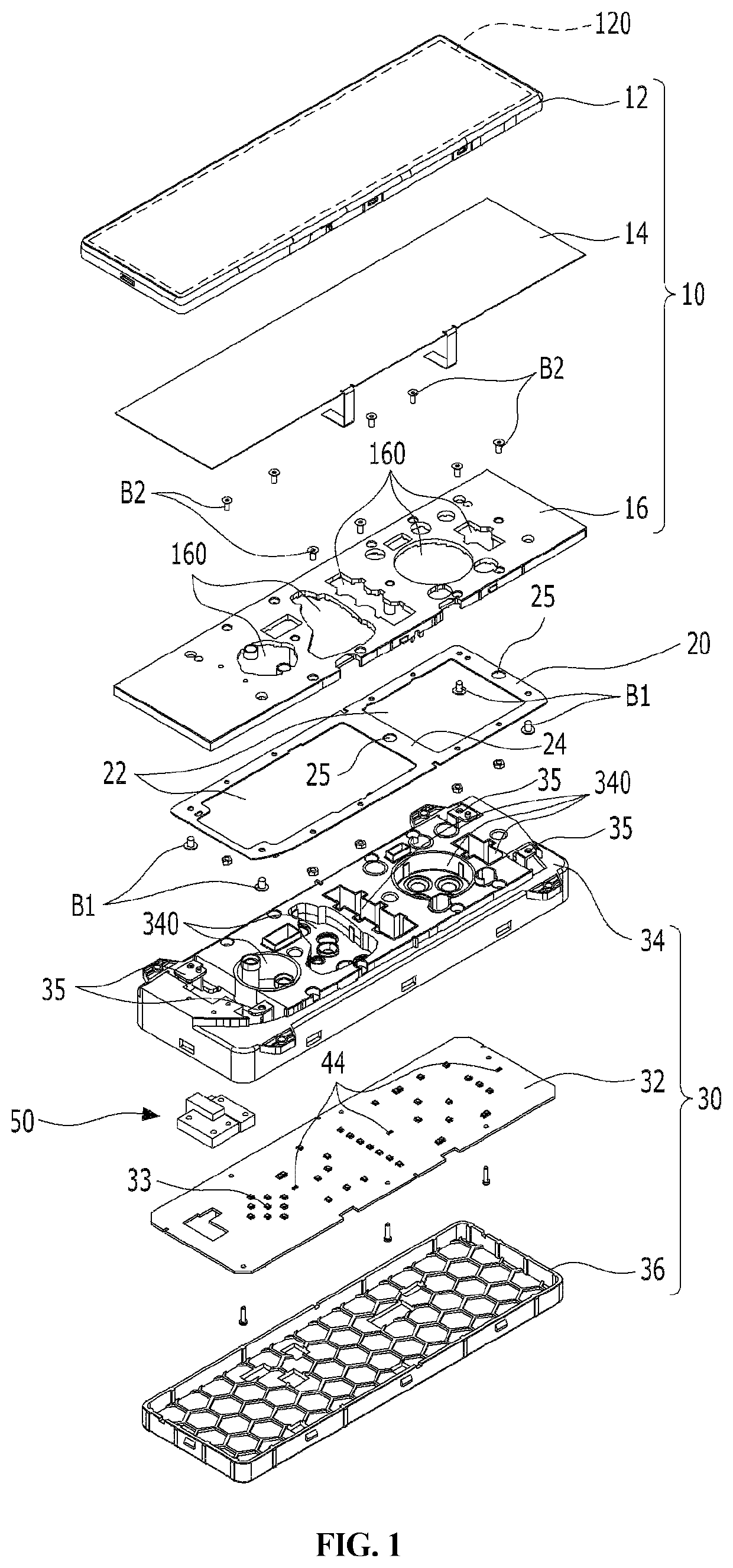
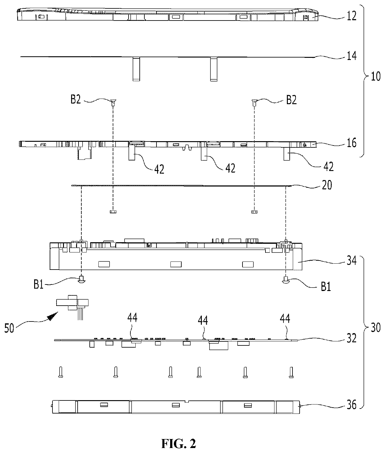
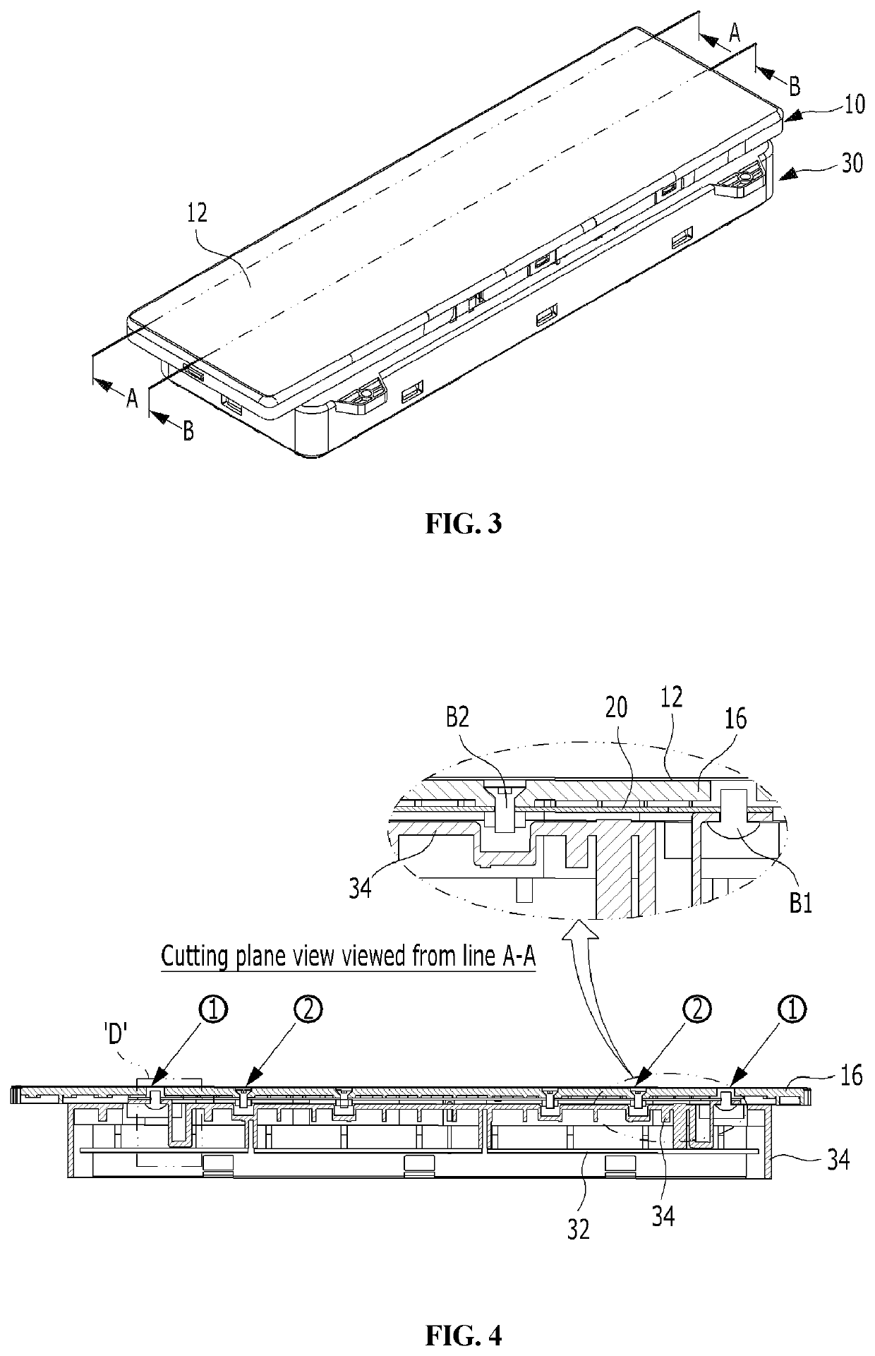
[0038]Hereinbelow, exemplary embodiments of the present disclosure will be described in detail with reference to the accompanying drawings.

[0039]Terms used in the specification are only used to describe specific embodiments and are not intended to limit the present disclosure. A singular expression includes a plural expression unless the context clearly dictates otherwise.

[0040]It is to be understood that a term such as “comprise”, “have”, or the like used in the present specification is intended to designate that a feature, number, step, operation, element, part, or a combination thereof described in the specification is present and not to preclude in advance the existence or addition of one or more other features, numbers, steps, operations, elements, parts, or combinations thereof

[0041]Also, terms such as first, second, and the like may be used to describe various elements, but the elements should not be limited by the terms. The above terms are used only for the purpose of disti...


PUM


Abstract

Proposed is a haptic reactive electrical switch including: a movable part including a floating panel having a touch area to which a user's touch is input and a holder coupled to the floating panel; a fixed part including a substrate and a casing configured to accommodate the substrate and be provided with at least two damping members; a vibration transmission plate configured to be interposed between the holder and the casing, thereby interconnecting the movable part and the fixed part; and an actuator configured to be operated to vibrate the holder and the vibration transmission plate coupled to the holder in a horizontal direction according to a user's touch input, wherein each of the damping members is configured in a form of a single object integrated into the casing, and an end part of one side thereof protrudes to a portion above the casing.

Description

CROSS REFERENCE TO RELATED APPLICATION[0001]The present application claims priority to Korean Patent Application No. 10-2021-0050124, filed Apr. 16, 2021, the entire content of which is incorporated herein for all purposes by this reference.BACKGROUND OF THE INVENTION1. Field of the Invention[0002]The present disclosure relates to an electrical switch for a vehicle capable of outputting a command for executing a desired function through a user's touch input. More particularly, the present disclosure relates to a haptic reactive electrical switch that generates vibration when a user inputs a touch with a force no less than a predetermined force and transmits the vibration to a user's finger as a stimulus.2. Description of Related Art[0003]In the case of electrical switches applied to vehicles, recently, instead of an analog type in which a function execution command is input through a simple physical manipulation (for example, a push manipulation, a rotation manipulation, or the like...

Claims


Application Information

Patent Timeline
IPC IPC(8): H03K17/96
CPCH03K17/96H03K2217/96062H03K2217/960785H03K17/962G06F3/016G06F3/0414G06F3/0416H02N2/02H01H13/705
Inventor YANG, DAE YEON
Owner ALPS ELECTRIC KOREA
Learn More