Check patentability & draft patents in minutes with Patsnap Eureka AI!

Pick and place cap and connector assembly

a connector and cap technology, applied in the field of pick and place caps, can solve the problem that the components do not have a suitable surface for the vacuum head, and achieve the effect of convenient picking and placing, facilitating picking and placing, and facilitating the picking and placing of the connector

Inactive Publication Date: 2019-03-19
3M INNOVATIVE PROPERTIES CO
View PDF8 Cites 0 Cited by
  • Summary
  • Abstract
  • Description
  • Claims
  • Application Information

AI Technical Summary

Problems solved by technology

However, some components do not have a suitable surface for the vacuum head.

Method used


Image

  • Pick and place cap and connector assembly
  • Pick and place cap and connector assembly
  • Pick and place cap and connector assembly

Examples


Embodiment Construction

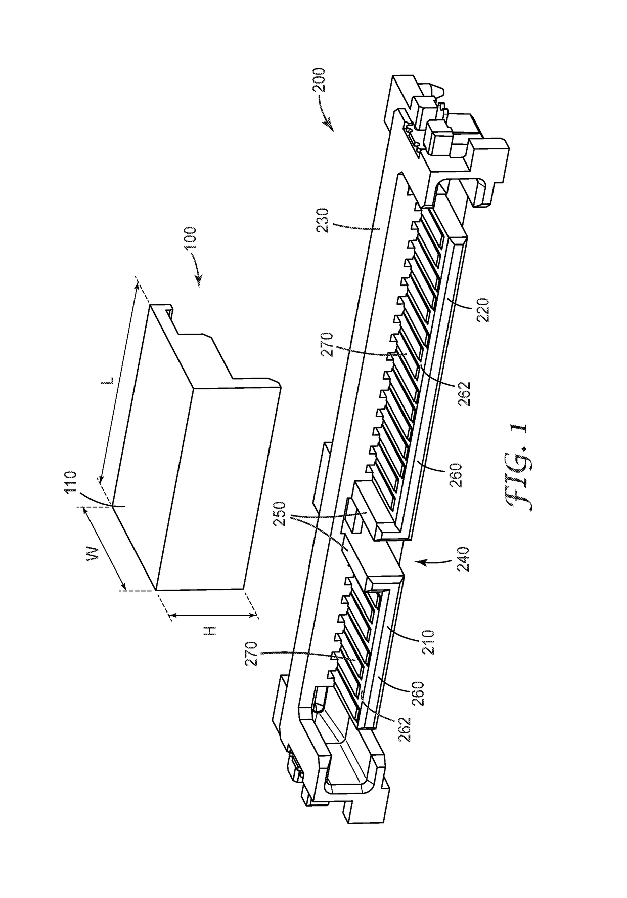
[0012]Some embodiments described herein are directed to a pick and place cap configured to facilitate picking and placing a connector when the cap is assembled to the connector. Features of the cap form a fictional fit with features of the connector that holds the cap to the connector during the pick and place process. The pick and place cap is configured to assemble to and / or disassemble from the connector along a height direction of the cap, e.g., along a direction that is perpendicular to the mating direction of the connector. Assembly / disassembly of the cap and connector along the direction perpendicular to the mating direction with a frictional fit enhances the pick and place process.

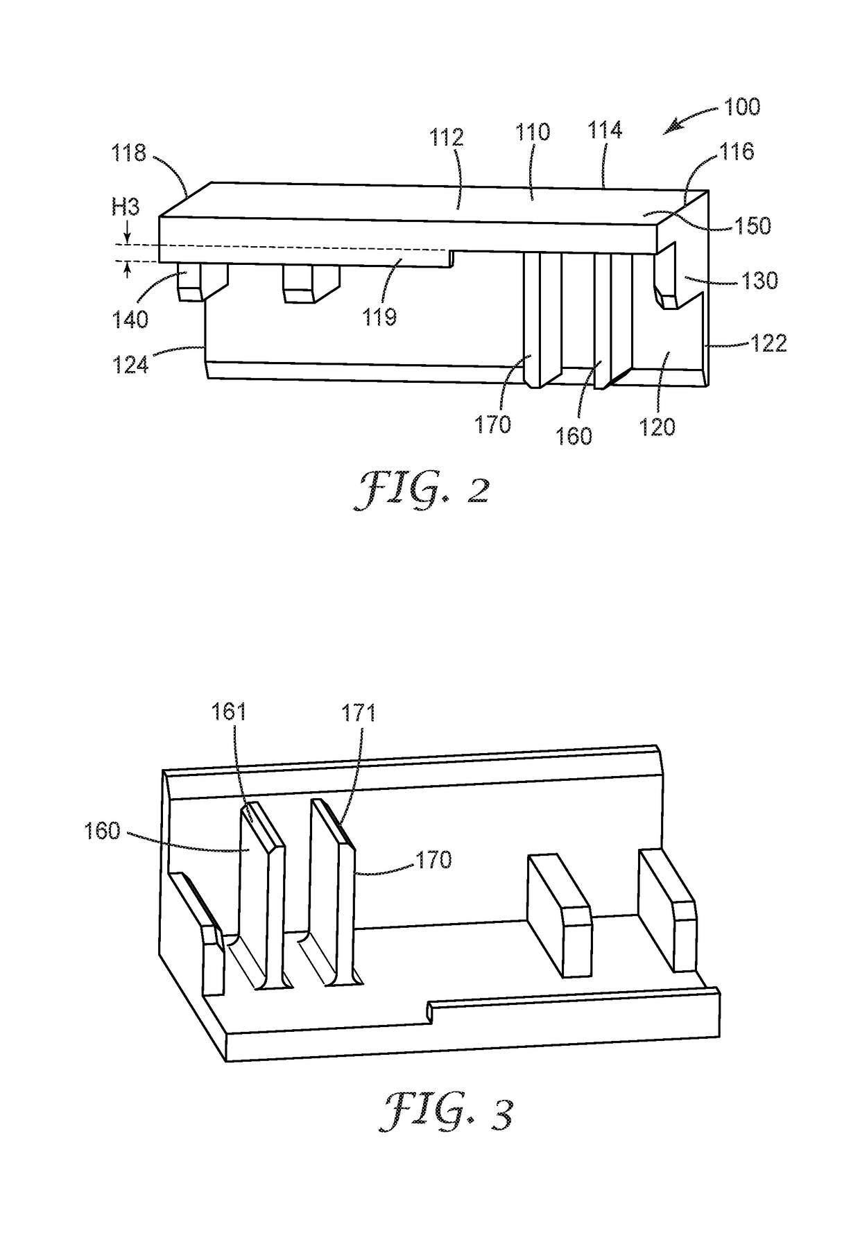
[0013]FIG. 1 illustrates a connector 200 and a cap 100 prior to assembling the cap 100 to the connector 200. FIG. 2 shows a perspective view of the cap 100. As illustrated in FIG. 1, the cap 100 includes a first wall 110 that defines a width, W, and a length, L, of the cap 100. A second wall 120 of...


PUM


Abstract

A pick and place cap is configured to facilitate picking and placing a connector when the cap is assembled to the connector. The cap includes a first wall defining a width, W, and a length, L of the cap. A second wall extends perpendicularly from the first wall and defines a height, H, of the cap. The cap also includes spaced apart parallel first, second, and third ribs extending from the first and second walls. Each of the first, second, and third ribs have the same first width, W1, and the same first height, H1. The first width and first height are less than the respective width and height of the cap. The cap includes spaced apart parallel fourth and fifth ribs disposed between and parallel to the second and third ribs. The fourth and fifth ribs are spaced part from the second wall and extend from the first wall. Each of the fourth and fifth ribs have the same second height, H2, which is greater than the first height, H1. Each of the fourth and fifth ribs have the same second width, W2, which is less than the first width, W1.

Description

TECHNICAL FIELD[0001]This disclosure relates generally to a pick and place cap for a connector and to connector assemblies that include a pick and place cap.BACKGROUND[0002]During the manufacture of electronic devices, some components are picked up from a magazine or tape and reel and placed on a circuit board to be soldered. During the pick and place operation the vacuum head of the pick and pack apparatus may apply suction to a surface of the component. However, some components do not have a suitable surface for the vacuum head. One alternative is to temporarily attach a cap to the component, so that the vacuum head attaches to the cap during the pick and place operation. The cap can then be removed after placement or soldering.BRIEF SUMMARY[0003]Some embodiments are directed to a pick and place cap configured to facilitate picking and placing a connector when the cap is assembled to the connector. The cap includes a first wall defining a width, W, and a length, L of the cap. A se...

Claims


Application Information

Patent Timeline
Patent Type & Authority Patents(United States)
IPC IPC(8): H01R13/44H01R43/20H01R43/02
CPCH01R43/205H01R43/0263
Inventor QIAO, YUNLONGBANDHU, SAUJIT
Owner 3M INNOVATIVE PROPERTIES CO
Features
  • R&D
  • Intellectual Property
  • Life Sciences
  • Materials
  • Tech Scout
  • Unparalleled Data Quality
  • Higher Quality Content
  • 60% Fewer Hallucinations
Learn More