Magnetic head for perpendicular magnetic recording including two side shields configured to enable a reduction in width of an end face of the main pole located in a medium facing surface and an increase in cross-sectional area of the main pole in the vicinity of the medium facing surface

a perpendicular magnetic and recording technology, applied in the direction of maintaining head carrier alignment, recording information storage, instruments, etc., can solve the problems of insufficient increase in recording density and inability to function satisfactorily, and achieve the effect of increasing recording density and improving write characteristics

Active Publication Date: 2019-07-30
HEADWAY TECH INC
View PDF3 Cites 0 Cited by
  • Summary
  • Abstract
  • Description
  • Claims
  • Application Information

AI Technical Summary

Benefits of technology

[0009]It is an object of the present invention to provide a magnetic head for perpendicular magnetic recording including a main pole and two side shields, the magnetic head being capable of providing both of improved write characteristics and increased recording density, and to provide a manufacturing method for the magnetic head.
[0032]According to the magnetic head for perpendicular magnetic recording and its manufacturing method of the present invention, the first side shield has the first and second sidewalls, and the second side shield has the third and fourth sidewalls. This configuration enables a reduction in width of the end face of the main pole located in the medium facing surface and an increase in cross-sectional area of the main pole in the vicinity of the medium facing surface, and prevents saturation of magnetic flux in the first and second side shields. The present invention thus makes it possible to achieve both of improved write characteristics and increased recording density.

Problems solved by technology

On the other hand, the reduced distance between the medium facing surface and the edge of each of the second to fourth sidewalls in this magnetic head disadvantageously renders the first and second side shields more susceptible to saturation of magnetic flux, thus causing the first and second side shields to become unable to function satisfactorily, resulting in insufficient increase in recording density.

Method used


Image

  • Magnetic head for perpendicular magnetic recording including two side shields configured to enable a reduction in width of an end face of the main pole located in a medium facing surface and an increase in cross-sectional area of the main pole in the vicinity of the medium facing surface
  • Magnetic head for perpendicular magnetic recording including two side shields configured to enable a reduction in width of an end face of the main pole located in a medium facing surface and an increase in cross-sectional area of the main pole in the vicinity of the medium facing surface
  • Magnetic head for perpendicular magnetic recording including two side shields configured to enable a reduction in width of an end face of the main pole located in a medium facing surface and an increase in cross-sectional area of the main pole in the vicinity of the medium facing surface

Examples


first embodiment

[0072]Preferred embodiments of the present invention will now be described in detail with reference to the drawings. First, reference is made to FIG. 7 to FIG. 10 to describe the configuration of a magnetic head for perpendicular magnetic recording (hereinafter simply referred to as magnetic head) according to a first embodiment of the invention. FIG. 7 is a cross-sectional view of the magnetic head according to the present embodiment. The arrow T in FIG. 7 indicates the direction of travel of a recording medium. FIG. 8 is a front view showing the medium facing surface of the magnetic head according to the present embodiment. FIG. 9 is a plan view showing a first coil portion of the magnetic head according to the present embodiment. FIG. 10 is a plan view showing a second coil portion of the magnetic head according to the present embodiment. In FIG. 8 to FIG. 10, the arrow TW indicates the track width direction.

[0073]The magnetic head according to the present embodiment is for use i...

second embodiment

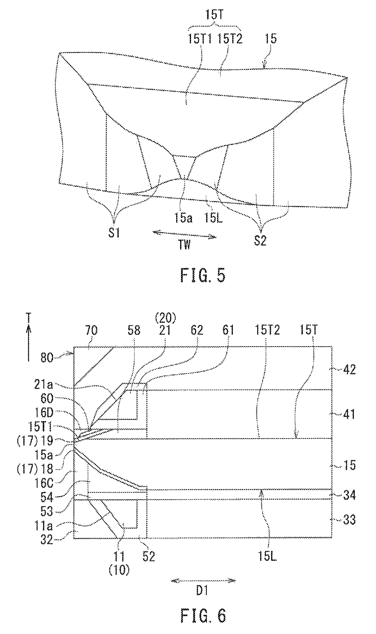
[0170]A magnetic head according to a second embodiment of the present invention will now be described with reference to FIG. 18. FIG. 18 is a perspective view showing part of a main pole and first and second side shields in the vicinity of a medium facing surface in the magnetic head according to the present embodiment.

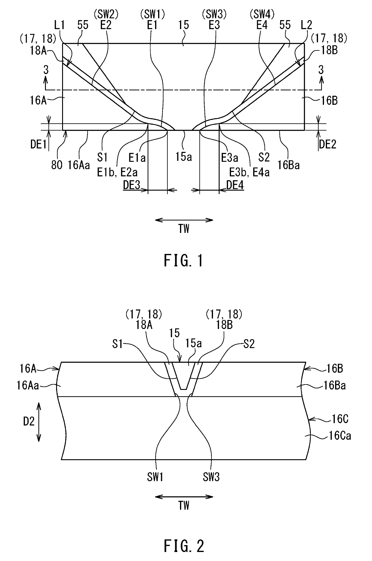
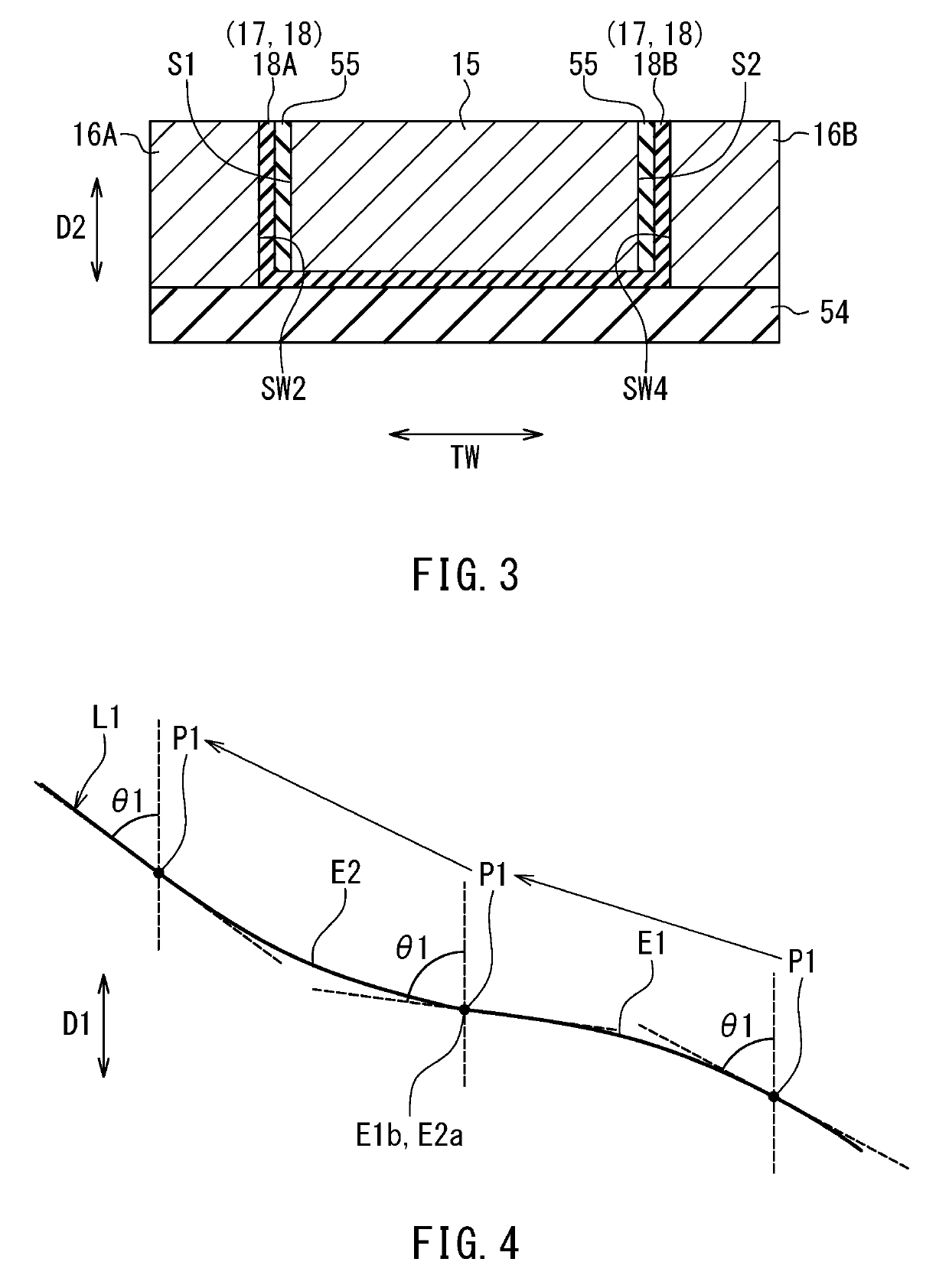
[0171]In the present embodiment, the shapes of the main pole 15 and the first and second side shields 16A and 16B are different from those in the first embodiment. In the present embodiment, the projecting portion of the first edge E1 of the first sidewall SW1 of the first side shield 16A projecting toward the main pole 15 is a corner and its surroundings located closer to the main pole 15 relative to a straight line connecting the front end E1a and the rear end E1b. The second edge E2 of the second sidewall SW2 of the first side shield 16A is shaped into a curve concaved away from the main pole 15. The fifth edge E5 of the fifth sidewall SW5 of the first side shield ...

modification examples

[0180]A first and a second modification example of the magnetic head according to the present embodiment will now be described. First, the first modification example will be described with reference to FIG. 21 and FIG. 22. FIG. 21 is a perspective view showing part of the main pole 15 and the first and second side shields 16A and 16B in the vicinity of the medium facing surface 80 in the first modification example. FIG. 22 is a plan view showing part of the main pole 15 and the first and second side shields 16A and 16B in the vicinity of the medium facing surface 80 in the first modification example.

[0181]In the first modification example, the projecting portion of the first edge E1 of the first sidewall SW1 of the first side shield 16A projecting toward the main pole 15 is a curved portion passing through a portion closer to the main pole 15 relative to the straight line connecting the front end E1a and the rear end E1b. The second edge E2 of the second sidewall SW2 of the first si...


PUM

PropertyMeasurementUnit
distanceaaaaaaaaaa
distanceaaaaaaaaaa
thicknessaaaaaaaaaa

Abstract

A first side shield has a first sidewall and a second sidewall, and a second side shield has a third sidewall and a fourth sidewall. The first to fourth sidewalls have first to fourth edges, respectively, that are farthest from a top surface of a substrate. The distance between a rear end of the first edge and a rear end of the third edge in a track width direction is greater than the distance between a front end of the first edge and a front end of the third edge in the track width direction. The distance between the second edge and the fourth edge in the track width direction increases with increasing distance from the medium facing surface.

Description

BACKGROUND OF THE INVENTION1. Field of the Invention[0001]The present invention relates to a magnetic head for perpendicular magnetic recording that is used for writing data on a recording medium by means of a perpendicular magnetic recording system, and more specifically, to a magnetic head for perpendicular magnetic recording that has two side shields.2. Description of the Related Art[0002]The recording systems of magnetic read / write apparatuses include a longitudinal magnetic recording system wherein signals are magnetized in a direction along the plane of a recording medium (the longitudinal direction) and a perpendicular magnetic recording system wherein signals are magnetized in a direction perpendicular to the plane of a recording medium. It is known that the perpendicular magnetic recording system is harder to be affected by thermal fluctuation of the recording medium and capable of providing higher linear recording density when compared with the longitudinal magnetic record...

Claims


Application Information

Patent Timeline
Patent Type & Authority Patents(United States)
IPC IPC(8): G11B5/11G11B5/31G11B5/127G11B5/60
CPCG11B5/3116G11B5/11G11B5/112G11B5/1278G11B5/3163G11B5/6082G11B5/315Y10T29/49052Y10T29/49046
Inventor SASAKI, YOSHITAKAITO, HIROYUKISATO, KAZUKIARAKI, HIRONORIIKEGAWA, YUKINORINOMURA, YOJI
Owner HEADWAY TECH INC
Why Eureka
Try Eureka