Magnetic head including a main pole and a write shield to provide improved write characteristics without compromising the function of the write shield

Active Publication Date: 2016-11-08
HEADWAY TECH INC
View PDF14 Cites 5 Cited by
  • Summary
  • Abstract
  • Description
  • Claims
  • Application Information

AI Technical Summary

Benefits of technology

[0021]It is an object of the present invention to provide a magnetic head that achieve

Problems solved by technology

A magnetic head provided with a wrap-around shield suffers from the problem that when a large amount of magnetic flux leaks from the main pole to the wrap-around shield, particularly to the leading shield and the first and second side shields, there occurs reductions in the write magnetic field strength and the aforementioned gradient of change at the top edge of the end face of the main pole or in the vicinity of the top edge, and the write characteristics are thereby degraded.
However, because of the small distance between the main pole and the leading shield, flux

Method used


Image

  • Magnetic head including a main pole and a write shield to provide improved write characteristics without compromising the function of the write shield
  • Magnetic head including a main pole and a write shield to provide improved write characteristics without compromising the function of the write shield
  • Magnetic head including a main pole and a write shield to provide improved write characteristics without compromising the function of the write shield

Examples


Embodiment Construction

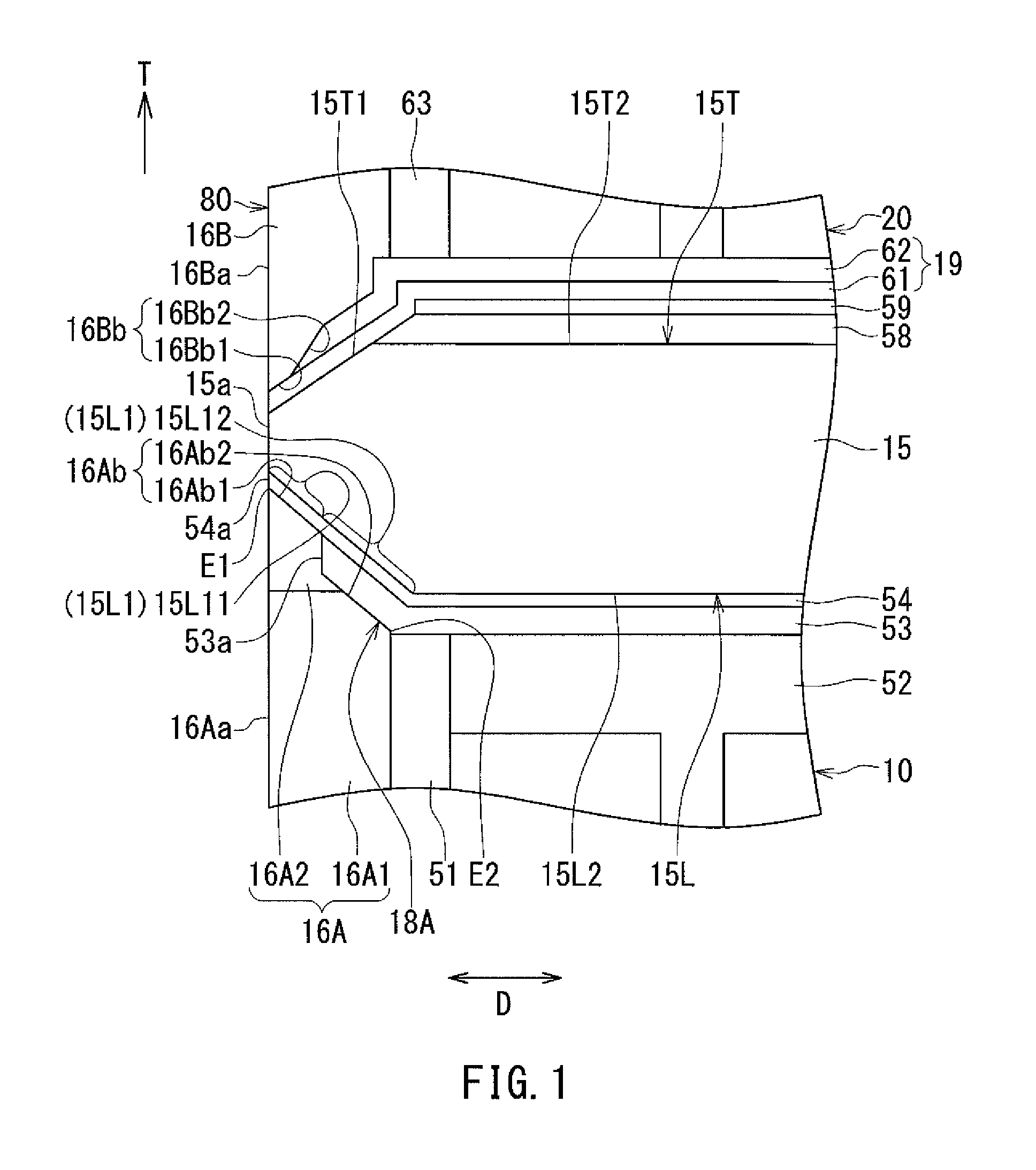
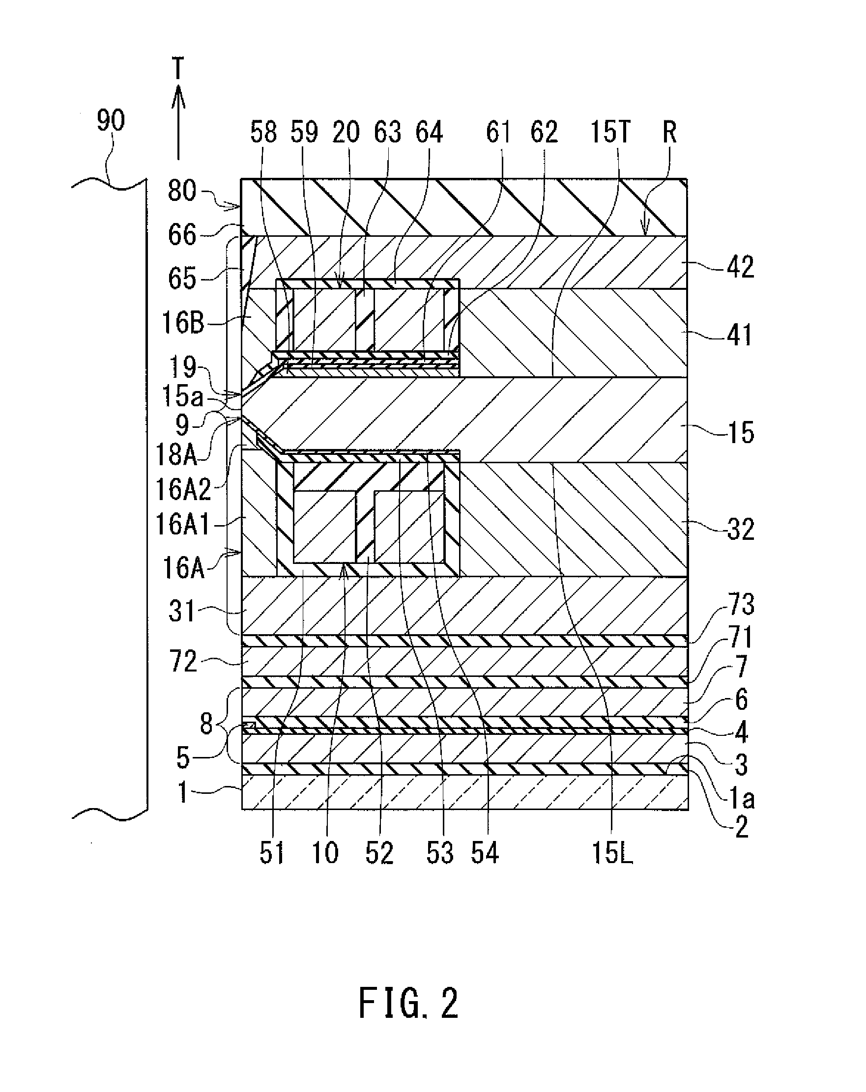
[0059]A preferred embodiment of the present invention will now be described in detail with reference to the drawings. First, reference is made to FIG. 2 to FIG. 5 to describe the configuration of a magnetic head according to an embodiment of the invention. FIG. 2 is a cross-sectional view of the magnetic head according to the embodiment. The arrow labeled T in FIG. 2 indicates the direction of travel of a recording medium. FIG. 3 is a front view showing the medium facing surface of the magnetic head according to the embodiment. FIG. 4 is a plan view showing a first coil portion of a coil of the magnetic head according to the embodiment. FIG. 5 is a plan view showing a second coil portion of the coil of the magnetic head according to the embodiment. In FIG. 3 to FIG. 5, the arrow labeled TW indicates the track width direction.

[0060]The magnetic head according to the embodiment is intended for perpendicular magnetic recording. The magnetic head according to the embodiment is for use i...


PUM


Abstract

A magnetic head includes a main pole, a write shield and a gap section. The write shield includes a leading shield having a top surface opposed to a bottom end of the main pole. The gap section includes a leading gap section for separating the leading shield from the bottom end of the main pole. The leading gap section is formed using a first nonmagnetic layer and a second nonmagnetic layer. The first nonmagnetic layer has a first front end located closest to but at a distance from the medium facing surface. The second nonmagnetic layer has a second front end located in the medium facing surface.

Description

BACKGROUND OF THE INVENTION[0001]1. Field of the Invention[0002]The present invention relates to a magnetic head for use to write data on a recording medium by means of a perpendicular magnetic recording system, and more specifically, to a magnetic head including a main pole and a write shield.[0003]2. Description of the Related Art[0004]The recording systems of magnetic read / write apparatuses include a longitudinal magnetic recording system in which the magnetization of signals is directed along the plane of a recording medium (the longitudinal direction), and a perpendicular magnetic recording system in which the magnetization of signals is directed perpendicular to the plane of a recording medium. It is known that the perpendicular magnetic recording system is harder to be affected by thermal fluctuation of the recording medium and capable of providing higher linear recording density, compared with the longitudinal magnetic recording system.[0005]Magnetic heads for perpendicular ...

Claims


Application Information

Patent Timeline
IPC IPC(8): G11B5/31G11B5/147G11B5/265
CPCG11B5/315G11B5/147G11B5/2651G11B5/3169G11B5/1278G11B5/23G11B5/3116G11B5/3163
Inventor IKEGAWA, YUKINORISASAKI, YOSHITAKASATO, KAZUKITANEMURA, SHIGEKIARAKI, HIRONORITOMITA, SEIICHIRO
Owner HEADWAY TECH INC
Why Eureka
Try Eureka