Thin-film magnetic head having magnetic layer with non-magnetic layer therewithin

a thin film, non-magnetic layer technology, applied in shielding heads, instruments, data recording, etc., can solve the problems of affecting the quality of the shielding head, so as to achieve the effect of improving the write characteristi

Active Publication Date: 2011-06-14
TDK CORPARATION
View PDF11 Cites 2 Cited by
  • Summary
  • Abstract
  • Description
  • Claims
  • Application Information

AI Technical Summary

Benefits of technology

[0017]Therefore, an object of the present invention is to provide a thin-film magnetic head having improved write characteristics in the high-frequency band, an HGA provided with the thin-film magnetic head, and a magnetic disk drive apparatus provided with the HGA.
[0023]In the above-described thin-film magnetic head according to the present invention, providing the above-described non-magnetic layer causes the generation of an eddy-current in the upper magnetic layer to be suppressed, which drastically reduces the eddy-current loss and improves the magnetic permeability. Further, because at least the lower surface, the upper surface, the front surface and the rear surface are covered with magnetic material, the magnetic flux in the upper and lower magnetic layers does not receive significant resistance, which suppresses the leakage of the magnetic flux. As a result, the write characteristics in the high-frequency band are improved. Especially in the write characteristics, the sufficient write field intensity is maintained, the ATE and the TPTP due to write currents are suppressed, or the NLTS is reduced.
[0024]Further, in the above-described thin-film magnetic head according to the present invention, at least surfaces other than both side surfaces of the non-magnetic layer are preferably covered with magnetic material of at least one of the upper magnetic layer and the lower magnetic layer. Also, it is preferable that the non-magnetic layer is wholly covered with magnetic material of at least one of the upper magnetic layer and the lower magnetic layer. In these cases, the leakage of magnetic field can be more suppressed.
[0025]Further, in the above-described thin-film magnetic head according to the present invention, a portion of the front surface, a portion of the rear surface or portions of both side surfaces of the non-magnetic layer is preferably connected to a non-magnetic region covering the upper magnetic layer. In the case, only a portion of the rear surface of the non-magnetic layer is also preferably connected to a non-magnetic region covering the upper magnetic layer. Further in the case, it is also preferable that the upper magnetic layer has a gap in an end portion thereof on the side opposite to the ABS, on a cross-section parallel to the element formation surface of the non-magnetic layer, and the upper magnetic layer surrounds the non-magnetic layer except the gap. Providing the gap causes the formation of loop current circuit surrounding the non-magnetic layer to be prevented, which reduces the eddy-current in the upper magnetic layer.
[0034]In either head for perpendicular or longitudinal magnetic recording, the non-magnetic layer is preferably formed of a non-magnetic and electrically insulating material. In the case, the generation of the eddy-current is more suppressed, which reduces the eddy-current loss and improves the permeability.
[0037]The above-described thin-film magnetic head, HGA and magnetic disk drive apparatus according to the present invention can show improved write characteristics in the high-frequency band. As a result, excellent recording / reproducing characteristics can be obtained under the condition of higher recording density.

Problems solved by technology

The eddy-current loss increases as data signals have higher frequency, and causes the write characteristics to be degraded by disturbing the response of the magnetization of the magnetic layers to the signal field.
However, even using the above-described conventional techniques utilizing the non-magnetic insulating layer (film) within the core in a certain form, there has been a problem that sufficient write characteristics in the high-frequency band is difficult to be obtained.
That is to say, there has been a problem of the difficulty in obtaining sufficient write field intensity, of the occurrence of adjacent track erase (ATE), of the increase in thermal pole tip protrusion (TPTP) due to write currents, and further of the increase in non-linear transition shift (NLTS).
As a result, a magnetic flux leaks out from the end, which reduces the intensity of the essential write field in the write gap position.
Also, the technique described in Japanese Patent Publication 11-25419A has the same problem, in which the non-magnetic insulating layer can reach the end on the opposed-to-medium surface side, as well as the end on the side opposite to the opposed-to-medium surface.
In the technique, the thickness of the non-magnetic insulating layer is adjusted to deal with this magnetic flux leakage problem, however, the case may occur that such thin-film magnetic heads cannot sufficiently corresponds to further miniaturization and higher frequency of data signals.
Moreover, the technique requires that the saturation magnetic flux density of the first magnetic film is set higher than that of the second magnetic flux density, which restricts the design of the magnetic circuit.
When the end of the magnetic head element has a contact with the surface of the magnetic disk due to the TPTP, the frictional heat by the contact causes the electric resistance of a magnetoresistive (MR) effect element for reading data signals to be changed, so that a problem (thermal asperity) such as the occurrence of abnormal signals is likely to occur, and further, the probability of crash becomes high.
The increase in the NLTS has a possibility to bring a negative effect to the demodulation of data signals.
However, the above-described conventional techniques just utilizing the non-magnetic insulating layer (film) within the core have had no consideration for suppressing / reducing these phenomena.

Method used


Image

  • Thin-film magnetic head having magnetic layer with non-magnetic layer therewithin
  • Thin-film magnetic head having magnetic layer with non-magnetic layer therewithin
  • Thin-film magnetic head having magnetic layer with non-magnetic layer therewithin

Examples


Embodiment Construction

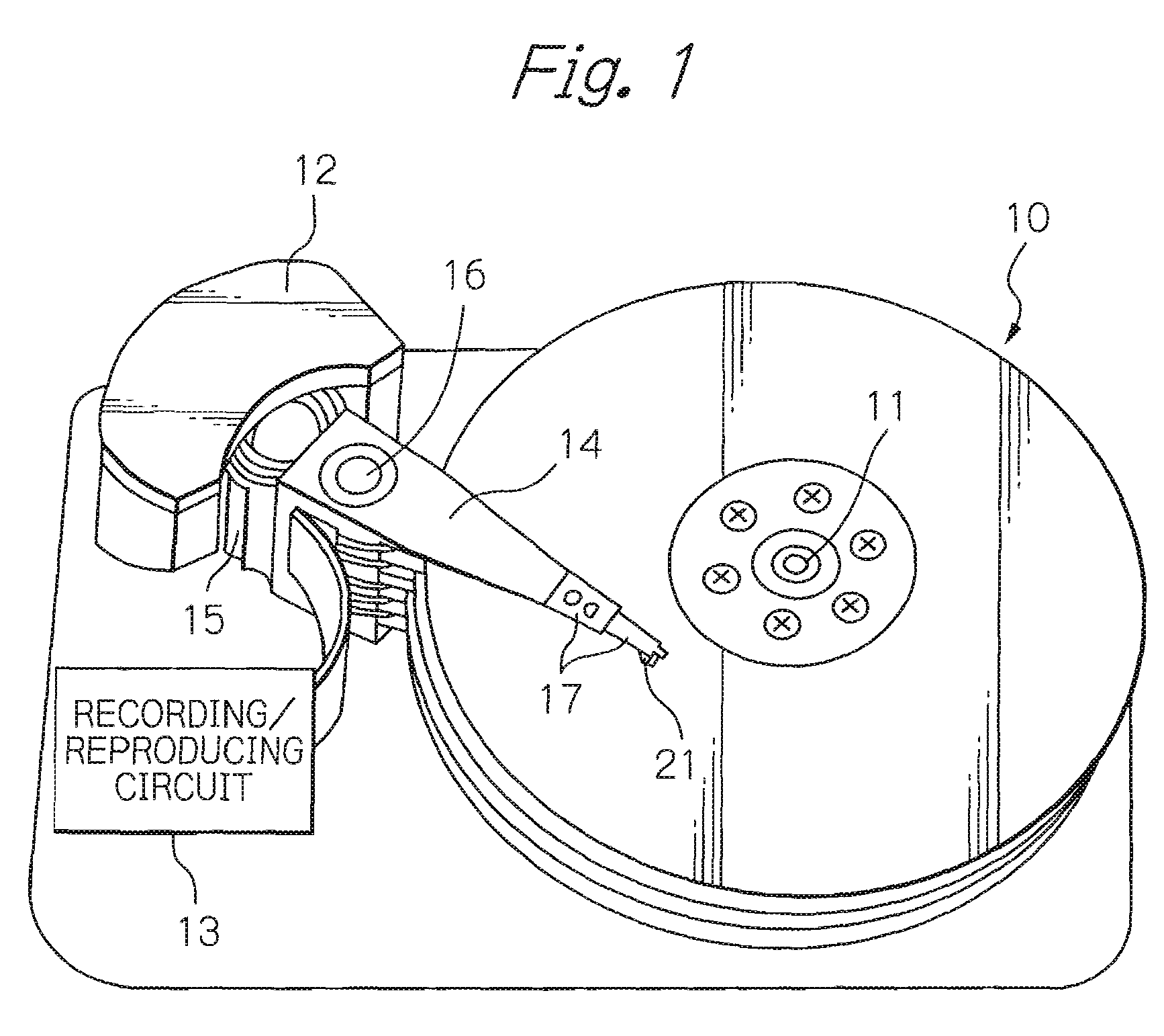
[0055]FIG. 1 shows a perspective view schematically illustrating a configuration of a main portion of an embodiment of the magnetic disk drive apparatus according to the present invention.

[0056]In FIG. 1, reference numeral 10 denotes multiple magnetic disks that rotate about the spindle of a spindle motor 11, 12 denotes an assembly carriage device for positioning a thin-film magnetic head (slider) 21 above a track, and 13 denotes a recording / reproducing circuit for controlling read / write operations of the thin-film magnetic head.

[0057]The assembly carriage device 12 is provided with multiple drive arms 14. The drive arms 14 are capable of angular-pivoting about a pivot bearing axis 16 driven by a voice coil motor (VCM) 15 and are stacked along the axis 16. An HGA 17 is attached in the end of each drive arm 14. Each HGA 17 is provided with a thin-film magnetic head (slider) 21 in such a manner that the slider 21 faces the surface of each magnetic disk 10. The numbers of magnetic disk...


PUM

PropertyMeasurementUnit
thicknessaaaaaaaaaa
eddy-current lossaaaaaaaaaa
thicknessaaaaaaaaaa

Abstract

Provided is a thin-film magnetic having improved write characteristics in the high-frequency band. The head comprises an electromagnetic coil element comprising upper and lower magnetic layers, a write gap layer and a write coil layer, and in the electromagnetic coil element, at least one non-magnetic layer is provided within the upper magnetic layer, and further, an upper surface, a lower surface, at least a portion of a front surface and at least a portion of a rear surface of the non-magnetic layer are covered with magnetic material of at least one of the upper magnetic layer and the lower magnetic layer.

Description

PRIORITY CLAIM[0001]This application claims priorities from Japanese patent application No. 2006-184563, filed on Jul. 4, 2006 and Japanese patent application No. 2006-279946, filed on Oct. 13, 2006, which are incorporated herein by reference.BACKGROUND OF THE INVENTION[0002]1. Field of the Invention[0003]The present invention relates to a thin-film magnetic head for magnetic recording including an electromagnetic coil element having a magnetic layer with a non-magnetic layer therewithin, a head gimbal assembly (HGA) provided with the thin-film magnetic head, and a magnetic disk drive apparatus provided with the HGA.[0004]2. Description of the Related Art[0005]With the increasing demand for small, and yet high-capacity magnetic disk drive apparatus in recent years, further improvements in recording density have become essential. One of the important factors for increasing recording density is an improvement in write characteristics of thin-film magnetic heads in the high-frequency b...

Claims


Application Information

Patent Timeline
Patent Type & Authority Patents(United States)
IPC IPC(8): G11B5/31
CPCG11B5/11G11B5/1278G11B5/3143G11B5/3136G11B5/3116
Inventor ANAGAWA, KENKICHIHIRABAYASHI, HIRAKU
Owner TDK CORPARATION
Why Eureka
Try Eureka