Drain and drain leveling mechanism

a technology of drain and leveling mechanism, which is applied in the direction of water installation, sewer system, construction, etc., can solve the problems of not always completely level floors, and achieve the effect of preventing accidental injuries of objects, easy and quick adjustment with minimal steps, and increasing the ease and efficiency of adjusting the floor drain

Active Publication Date: 2019-08-06
RECTORSEAL LLC
View PDF50 Cites 1 Cited by
  • Summary
  • Abstract
  • Description
  • Claims
  • Application Information

AI Technical Summary

Benefits of technology

[0007]It is often desirable for a floor drain to be relatively flush with the level of the floor, thereby preventing accidental injuries from objects catching on a lip of the drain or the floor or other inconveniences associated with a floor drain that rises above or is set below the level of the floor. In many instances, modifications to a floor, such as adding, modifying, or removing a floor surface, may adjust the height of the floor. Additionally, a floor may not always be completely level relative to the drain pipe. In these instances, it can be desirable to provide a floor drain that can be adjusted in height and / or angle. Such a floor drain can be adjusted to help ensure that the plate remains generally level with the floor. Additionally, in various embodiments it can be desirable for an adjustable floor drain to be easily and quickly adjustable with minimal steps.
[0008]Various embodiments described herein present the advantage of allowing for adjustment of the height and / or angle of a floor drain grate without having to remove the grate from an adjustable drain apparatus. This can increase the ease and efficiency of adjusting the floor drain.
[0009]Various embodiments described herein provide additional features to improve the ease and efficiency of adjusting a floor drain apparatus. In some embodiments, a floor drain assembly or apparatus can include a leveling member that can be used to adjust the height and / or angle of a grate and that can simultaneously be used to attach different components of the floor drain assembly to each other. As a result, in some embodiments adjusting the height and / or angle of the grate requires the manipulation of no more than 3 screws.

Problems solved by technology

Additionally, a floor may not always be completely level relative to the drain pipe.

Method used


Image

  • Drain and drain leveling mechanism
  • Drain and drain leveling mechanism
  • Drain and drain leveling mechanism

Examples


Embodiment Construction

[0036]In the following discussion that addresses a number of embodiments and applications, reference is made to the accompanying drawings that form a part hereof, and in which is shown by way of illustration specific embodiments in which the embodiments described herein may be practiced. It is to be understood that other embodiments may be utilized and changes may be made without departing from the scope of the disclosure.

[0037]Various inventive features are described below that can each be used independently of one another or in combination with other features. However, any single inventive feature may not address all of the problems discussed above or only address one of the problems discussed above. Further, one or more of the problems discussed above may not be fully addressed by the features of each embodiment described below.

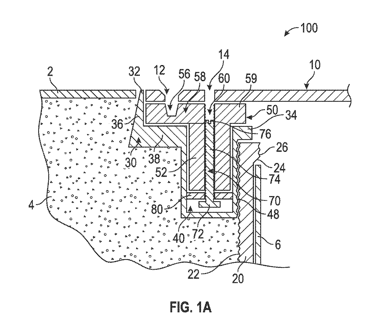
[0038]FIG. 1A illustrates one embodiment of an adjustable floor drain assembly or apparatus 100. In some embodiments, the floor drain 100 can be a cylindr...


PUM


Abstract

An adjustable floor drain apparatus includes a housing configured for positioning adjacent a drain pipe, a leveling frame configured to be positioned at least partially above the housing, a grate configured to be positioned at least partially above the leveling frame and secured to the leveling frame, and a leveling member. The leveling member can be configured such that actuating the leveling member adjusts the position of the grate relative to the housing while the leveling member remains fixed relative to the housing. The leveling member can be configured such that actuating the leveling member moves the leveling member relative to the grate and adjusts the position of the grate relative to the housing.

Description

INCORPORATION BY REFERENCE TO ANY PRIORITY APPLICATIONS[0001]Any and all applications for which a foreign or domestic priority claim is identified in the Application Data Sheet as filed with the present application, are hereby incorporated by reference in their entirety under 37 CFR 1.57. This application claims the benefit of priority under 35 U.S.C. § 119(e) of U.S. Provisional Application No. 62 / 023,685, filed on Jul. 11, 2014, and entitled “DRAIN AND DRAIN LEVELING MECHANISM,” the entire disclosure of which is incorporated herein by reference.BACKGROUND[0002]Field of the Disclosure[0003]The present disclosure relates in general to adjustable drains. Such drains can be used in buildings, floors, basements, exterior areas or other areas that require drainage, as well as for urinals and other waste handling devices connected to a sewer or drain conduit. Such drains can also be used for clean outs.[0004]Description of the Related Art[0005]Many varieties of adjustable drains exist, e...

Claims


Application Information

Patent Timeline
Patent Type & Authority Patents(United States)
IPC IPC(8): E03F5/04
CPCE03F5/0407E03F2005/0414E03F2005/0413
Inventor HUBER, DONALD G.
Owner RECTORSEAL LLC
Why Eureka
Try Eureka