
Device for dismountably connecting two intersecting formwork beams
a technology of formwork beams and beams, which is applied in the direction of forms/shuttering/falseworks, shaping building parts, constructions, etc., can solve the problems of shortening the service life of the beams, requiring considerable manpower, and difficult to quantify the strength of the joint, so as to achieve constant and readily controlled clamping pressure, easy to apply, and low dependence on human action for mounting
- Summary
- Abstract
- Description
- Claims
- Application Information
AI Technical Summary
Benefits of technology
Problems solved by technology
Method used
Image

Examples
Embodiment Construction
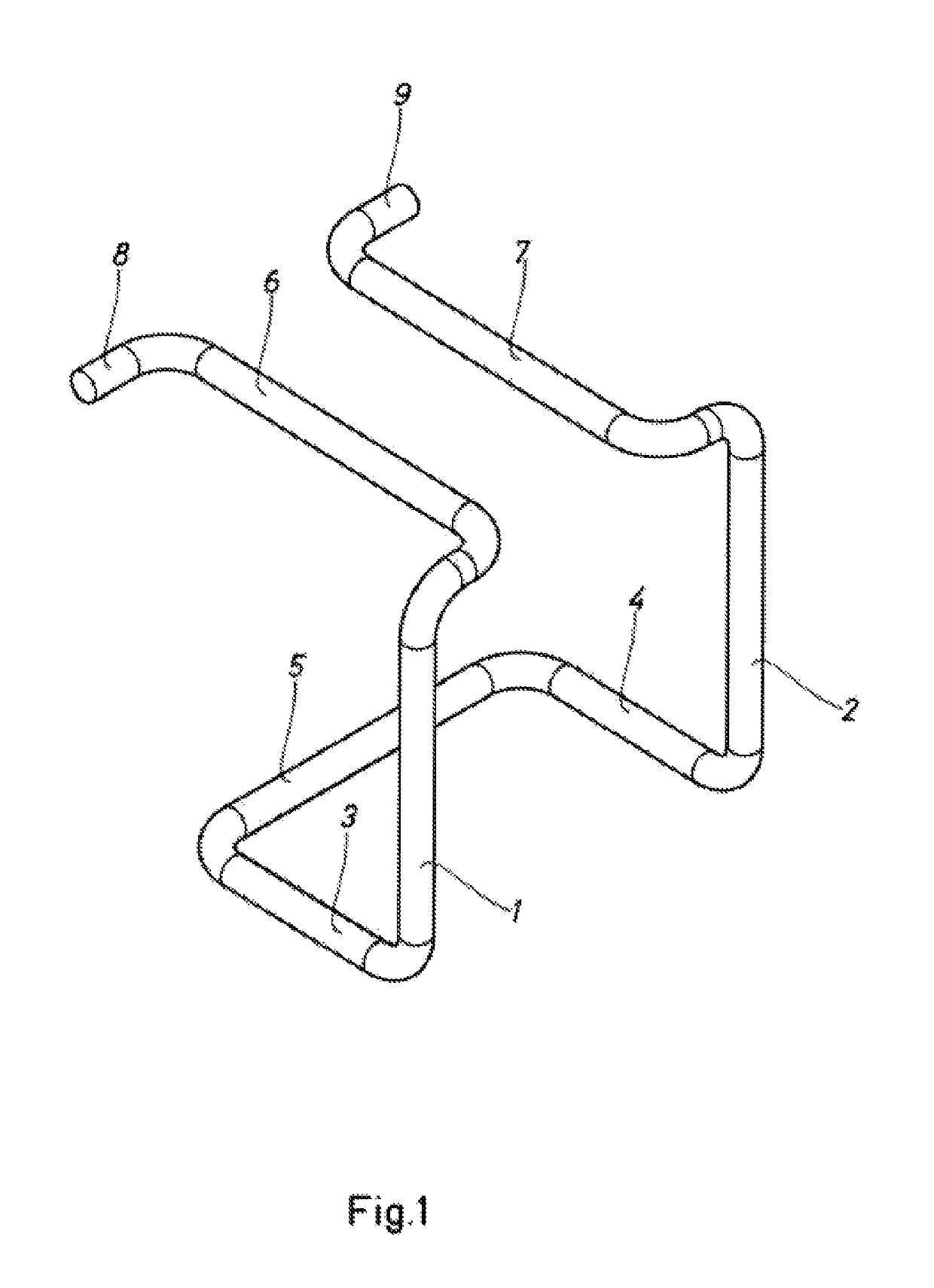
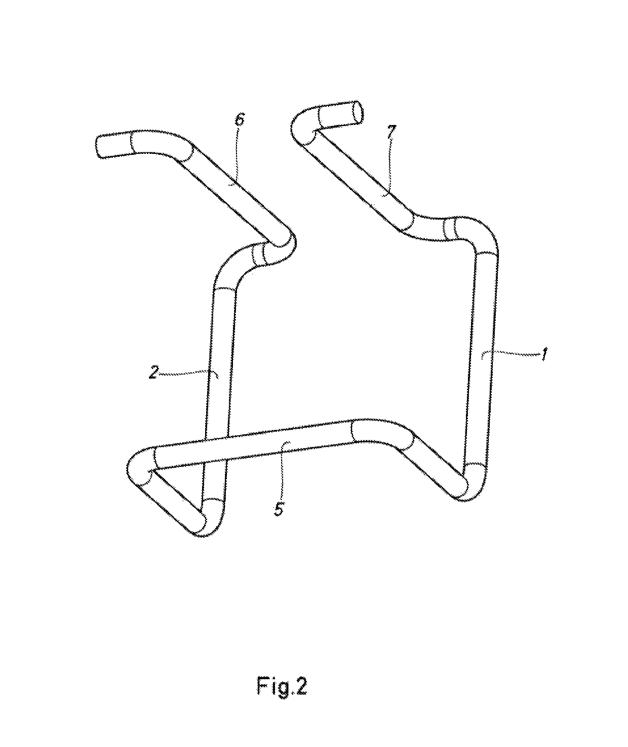
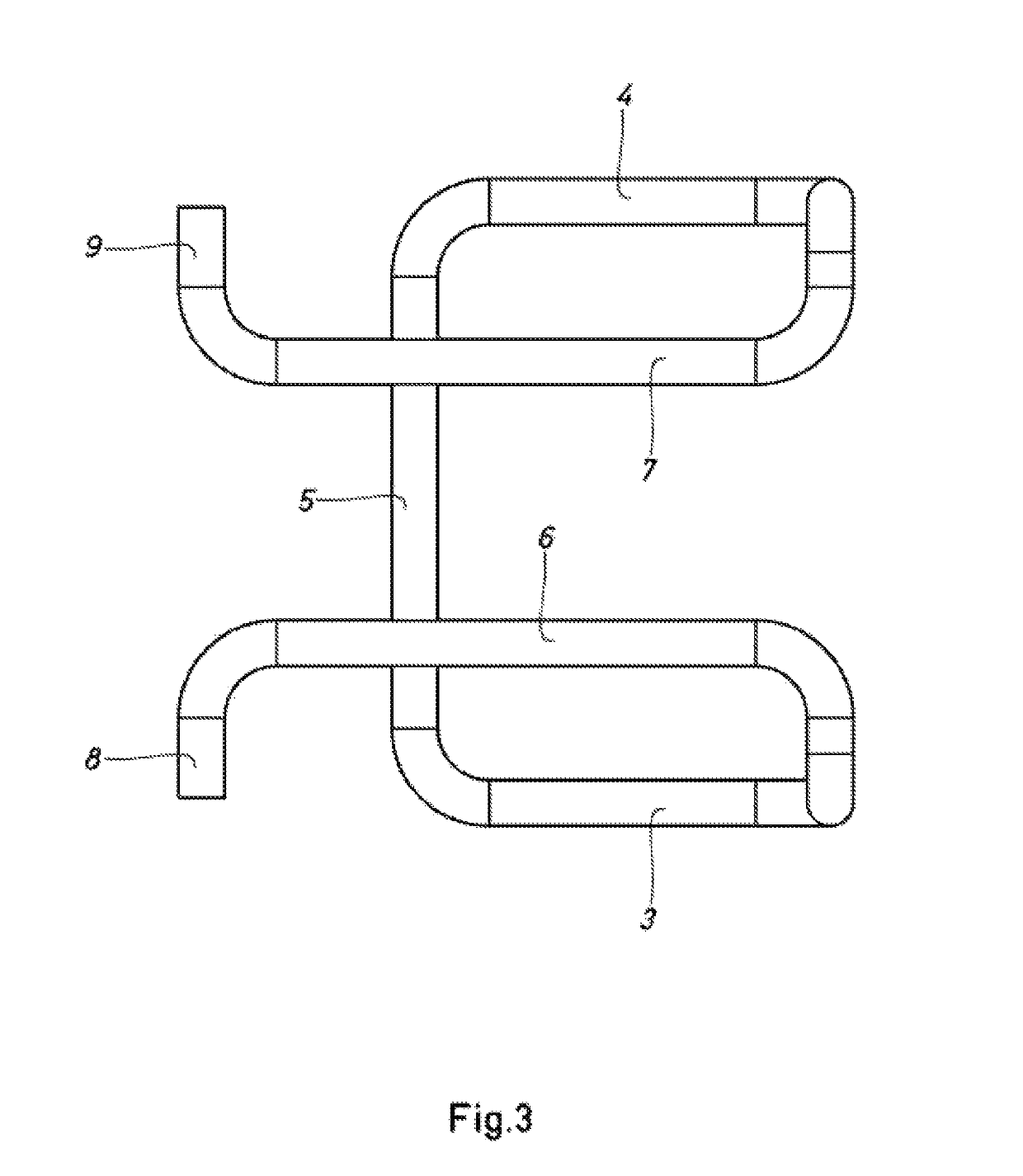
[0063]As can be seen in FIG. 1 to 3, the device for dismountably connecting intersecting formwork beams, according to the present invention, comprises two arms that diverge slightly upwards -1- and -2-, and are joined to respective, substantially horizontal sections -3- and -4-, which together with a crosspiece -5- form a U- or V-shaped bridge. At the top, the arms -1- and -2- extend into respective straight, substantially horizontal extensions -6- and -7-. The various components mentioned, together forming in succession the connection device based on a resilient steel rod, are joined by means of multiple curved elbows, which have not been specifically numbered for greater clarity of the figures. The straight extensions of the upper portion -6- and -7-end in respective folded regions -8- and -9- positioned in the same plane as determined by the extensions -6 -nd -7-.
[0064]FIGS. 4 and 5 are a perspective view and a side elevation view, respectively, of a version of the device of the ...
PUM
 Abstract
Description
Claims
Application Information