Supercharge Your Innovation With Domain-Expert AI Agents!

Hydraulic machine with floating cylinders

a technology of floating cylinders and hydraulic machines, which is applied in the direction of reciprocating piston engines, positive displacement liquid engines, positive displacement engines, etc., can solve the problems of high number of components and hydraulic sealing zones, and achieve the effect of small overall dimensions and small number of components

Active Publication Date: 2019-09-03
MERLO GRP INNOVATION LAB
View PDF6 Cites 1 Cited by
  • Summary
  • Abstract
  • Description
  • Claims
  • Application Information

AI Technical Summary

Benefits of technology

The design achieves smaller overall dimensions and fewer components while maintaining efficient hydraulic sealing, allowing for flexible operation as both a pump and a motor with adjustable displacement.

Problems solved by technology

One of the problems of the solution described in the document WO03 / 058035 is the high number of components and hydraulic sealing zones.

Method used


Image

  • Hydraulic machine with floating cylinders
  • Hydraulic machine with floating cylinders
  • Hydraulic machine with floating cylinders

Examples


Embodiment Construction

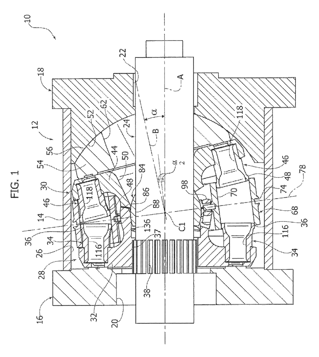
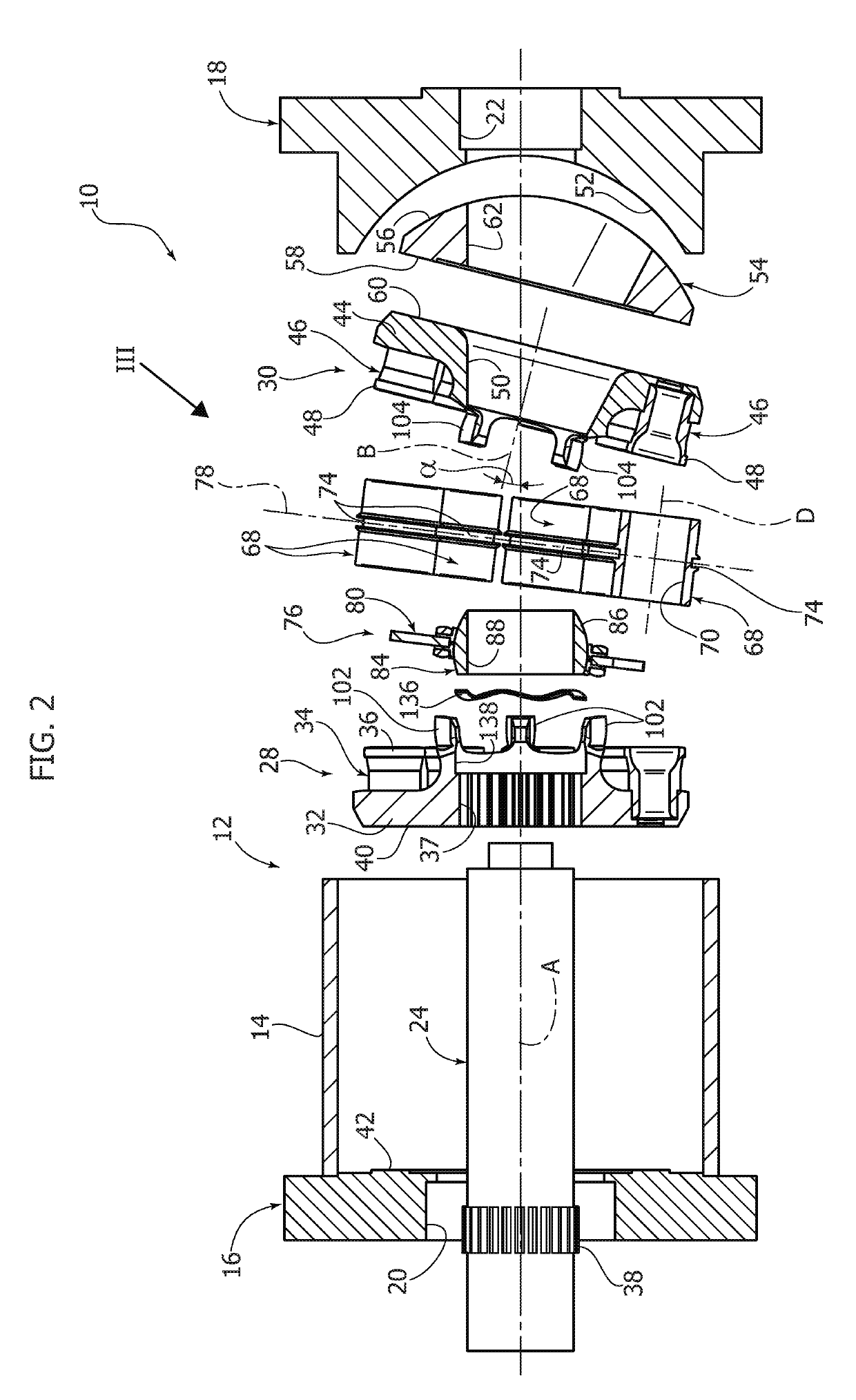
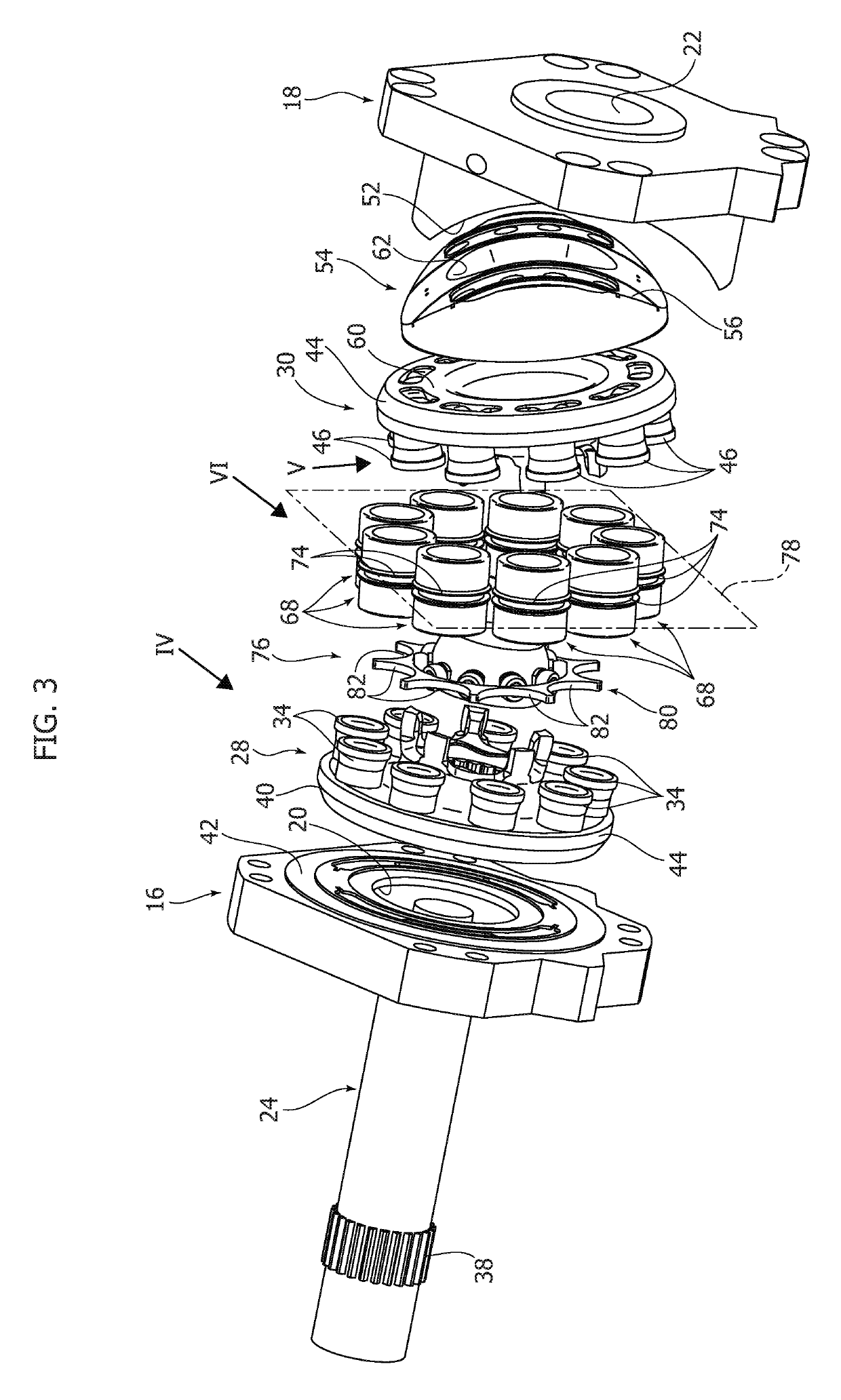
[0021]With reference to FIGS. 1 and 2, numeral 10 indicates a hydraulic machine according to the present invention. The hydraulic machine 10 can operate either as a pump or as a motor. The hydraulic machine 10 comprises a stationary casing 12 comprising a tubular central body 14, a first front plate 16 and a second front plate 18. The first and the second front plates 16, 18 are fixed to opposite ends of the central body 14. The first and the second front plates 16, 18 are provided with respective seats 20, 22 for bearings and seals (not shown), which support in rotation a shaft 24 rotatable with respect to the casing 12 about a main axis A.

[0022]The casing 12 defines a chamber 26 within which a first rotor 28 and a second rotor 30 are arranged.

[0023]The first rotor 28 comprises a first rotor body 32 and a plurality of first pistons 34 fixed to the first rotor body 32. The first rotor body 32 has a splined hole 37 that engages a splined portion 38 of the shaft 24. Thus, the first ro...


PUM


Abstract

A hydraulic machine comprising: an outer casing comprising a first front plate and a second front plate, a shaft rotatable about a main axis, a first rotor comprising a first rotor body rotatable with said shaft around said main axis, and a plurality of first pistons with respective spherical ring heads fixed to said first rotor body, a second rotor comprising a second rotor body and a plurality of second pistons with respective spherical ring heads, wherein the second rotor is rotatable about a secondary axis, inclined with respect to said main axis, a plurality of sleeves that are separate and independent from each other, each having a cylinder open at opposite ends and engaged on opposite sides by a first piston and by a second piston.

Description

CROSS-REFERENCE TO RELATED APPLICATIONS[0001]This application claims benefit of Italian patent application number 102015000078409, filed Nov. 30, 2015, which is herein incorporated by reference.BACKGROUND OF THE INVENTION[0002]Field of the Invention[0003]The present invention relates to hydraulic machines with pistons. More precisely, the invention relates to a hydraulic machine, usable as a pump and as a motor, of the type comprising a first rotor rotatable about a first axis and a second rotor rotatable about a second axis inclined with respect to the first axis.[0004]Description of Prior Art[0005]The document WO03 / 058035 describes a hydraulic device comprising a casing, a first rotor rotatable about a first axis and carrying a first and a second series of pistons protruding from opposite sides of the first rotor. A second and a third rotor are arranged on opposite sides of the first rotor and are rotatable about their respective axes that are inclined with respect to the rotation...

Claims


Application Information

Patent Timeline
Patent Type & Authority Patents(United States)
IPC IPC(8): F03C1/06F04B1/32F04B1/22F03C1/40F04B1/12F04B1/20F03C1/32
CPCF04B1/22F04B1/124F04B1/20F04B1/2078F03C1/0636F03C1/0668F03C1/0639F03C1/0652F03C1/0694F04B1/328F04B1/146F04B1/16F04B1/295F01B3/0038F01B3/0064F01B3/0044F15B2211/205F15B2211/7058
Inventor GALFRE, RENATOMERLO, AMILCARENEGRINI, STEFANO
Owner MERLO GRP INNOVATION LAB
Features
  • R&D
  • Intellectual Property
  • Life Sciences
  • Materials
  • Tech Scout
  • Unparalleled Data Quality
  • Higher Quality Content
  • 60% Fewer Hallucinations
Learn More