Unmanned aerial vehicle launching and landing system

a technology for unmanned aerial vehicles and landing systems, which is applied in the direction of aircrafts, launching/towing gear, transportation and packaging, etc., can solve the problems of imposing constraints on the use of unmanned aerial vehicles, not imparting a suitable solution, and leaving the problem of retrieving the aerial vehicles with the problem of being unable to carry out the operation, etc., to achieve remarkable reliability and safety features, easy maintenance and operation, and high rate

Active Publication Date: 2009-09-10
ELBIT SYST LTD
View PDF10 Cites 113 Cited by
  • Summary
  • Abstract
  • Description
  • Claims
  • Application Information

AI Technical Summary

Benefits of technology

[0017]Thus, at the period preceding this current invention, there existed the long felt and continuous need for a compact landing and launching UAV's system that would be distinguished by its small dimensions, installable on a relatively small mobile platform (for example, a missiles boat) while being integrated with the armament and detection systems aboard these platforms on the one hand but without causing interference to their battle operational modes and equipment, culminating in a launching and landing system that is easy to maintain and operate and that would impart UAV's launching and landing capability at a high rate and with remarkable reliability and safety features.

Problems solved by technology

As a rule, the constraints imposed on UAV's usage stems from the requirement of employing a rather long runway for their “take off's” (i. e., launching) and landings.
The major part of the kinetic energy is absorbed during the process due to the aerodynamic drag that is generated by the mobile braking device.
All the above cited systems and methods do not impart a suitable solution to the challenge presented by the tactical requirement of high rate launching and landing of an UAV from and upon a mobile platform whose dimensions are relatively small (for example, a vessel) as stated, which is really the challenge presented by the cited operational requirements.
Verily, the launching of a UAV might be aided by a pyrotechnic device (such as an accelerating rocket) that exhausts and is cast off away from the UAV after its launching, but even more than the environmental danger generated by such a device and its relatively high costs, we are still left with the problem of retrieving the aerial vehicle.
Landing a UAV by tying the aerial vehicle to a cable that is dropped off from the UAV, sending aloft hovering parachutes from the platform or setting up net means on the platform, as were described in the above cited patents documents, do not yet provide an adequate solution.

Method used


Image

  • Unmanned aerial vehicle launching and landing system
  • Unmanned aerial vehicle launching and landing system
  • Unmanned aerial vehicle launching and landing system

Examples


Embodiment Construction

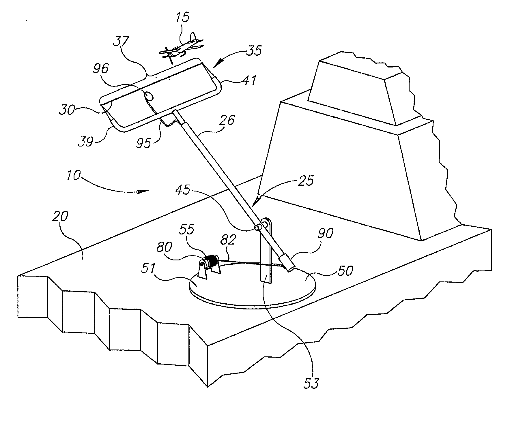
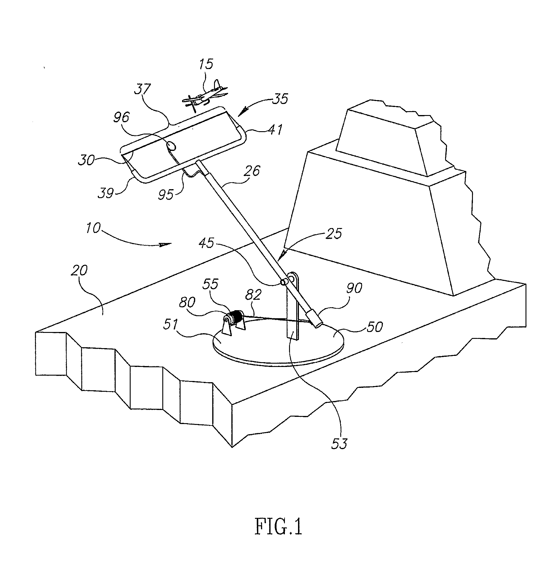
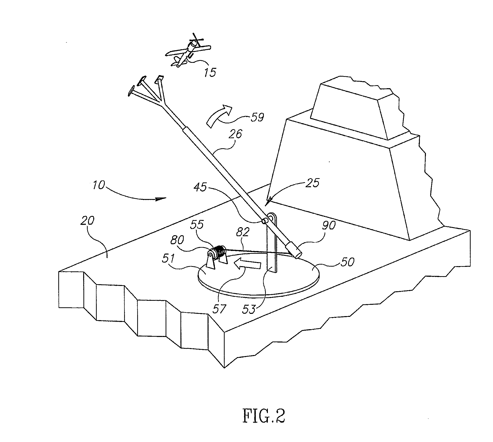
[0035]Let's refer to FIG. 1. FIG. 1 constitutes an illustration view of system 10 in accordance with a preferred embodiment of the present invention, the embodiment wherein the same system, with only minor changes that can be performed at the launching site, serves both for launching a UAV 15 and for landing it.

[0036]In the illustrated example, system 10 is mounted at the stern of a mobile platform that in this example is a missile boat 20, but any professional in this field would understand that a system in accordance with the invention might also be mounted on a myriad of other types and differing mobile (or also static) platforms, such as a vessel, a vehicle, a train or a post.

[0037]A system in accordance with the invention comprises a structure 25 that constitutes a sort of a mechanical slingshot structure.

[0038]A landing case of UAV 15 is illustrated in FIG. 1. In this case, assembly 35 is added in a dismountable manner to the central arm 26 of structure 25. The configuration o...


PUM


Abstract

The present invention relates to a system for landing UAV's. The system comprises a slingshot structure that includes arm based structure and an axis means installed along the arm of the structure and wherein it enables the arm to move around it in addition, the system comprises base means connecting the axis means to a platform at which the system is installable. The system also include a controlled pulling and braking means that connects between the arm of the structure and the platform upon which the system is installable and a stretchable elastic means installed in a stretched manner at a gap formed between two arms and set to connect with a landing UAV. At the landing phase, the controlled pulling and braking means of the system, essentially breaks the motion of the arm based structure that is propelled to revolve around the system's axis means, from a time that the UAV forms contact with the elastic means and with it propels the structure to move around the axis means.

Description

RELATED APPLICATION DATA[0001]This application is a continuation-in-part of International Application No. PCT / IL2007 / 000488 filed on Apr. 18, 2007, which claims the benefit of priority from Israeli Application No. 177185 filed on Jul. 31, 2006, the content of each of which is expressly incorporated herein in its entirety by this reference.FIELD OF THE INVENTION[0002]The present invention relates to the field of systems for launching and landing aircrafts in general, and specifically to systems for launching Unmanned Aerial Vehicles (herein after UAV) from a mobile or stationary platform wherein this platform has relatively small dimensions (for example, a vessel, a truck, a fenced area) and landing them on it at the completion of their flight.BACKGROUND OF THE INVENTION[0003]In the course of the recent years, the scope of utilizing UAV's grew and expanded noticeably, particularly for military tasks. As a rule, the constraints imposed on UAV's usage stems from the requirement of empl...

Claims


Application Information

Patent Timeline
Patent Type & Authority Applications(United States)
IPC IPC(8): B64F1/02B64F1/04
CPCB64C2201/084B64C2201/182B64F1/06B64F1/02B64F1/029B64F1/027B64U70/70B64U70/30
Inventor KARIV, AMNON
Owner ELBIT SYST LTD
Why Eureka
Try Eureka