Display device
a display device and display technology, applied in the field of display devices, can solve problems such as complicated device configuration, and achieve the effect of simple control and simple configuration
- Summary
- Abstract
- Description
- Claims
- Application Information
AI Technical Summary
Benefits of technology
Problems solved by technology
Method used
Image


Examples
example 1
[0305]A flat plate (SUMI-HOLIDAY, manufactured by Hikari Co., Ltd.) formed of polymethyl methacrylate (PMMA) and having a thickness of 2 mm and a size of 100×100 mm was prepared. The refractive index of the flat plate is 1.48.
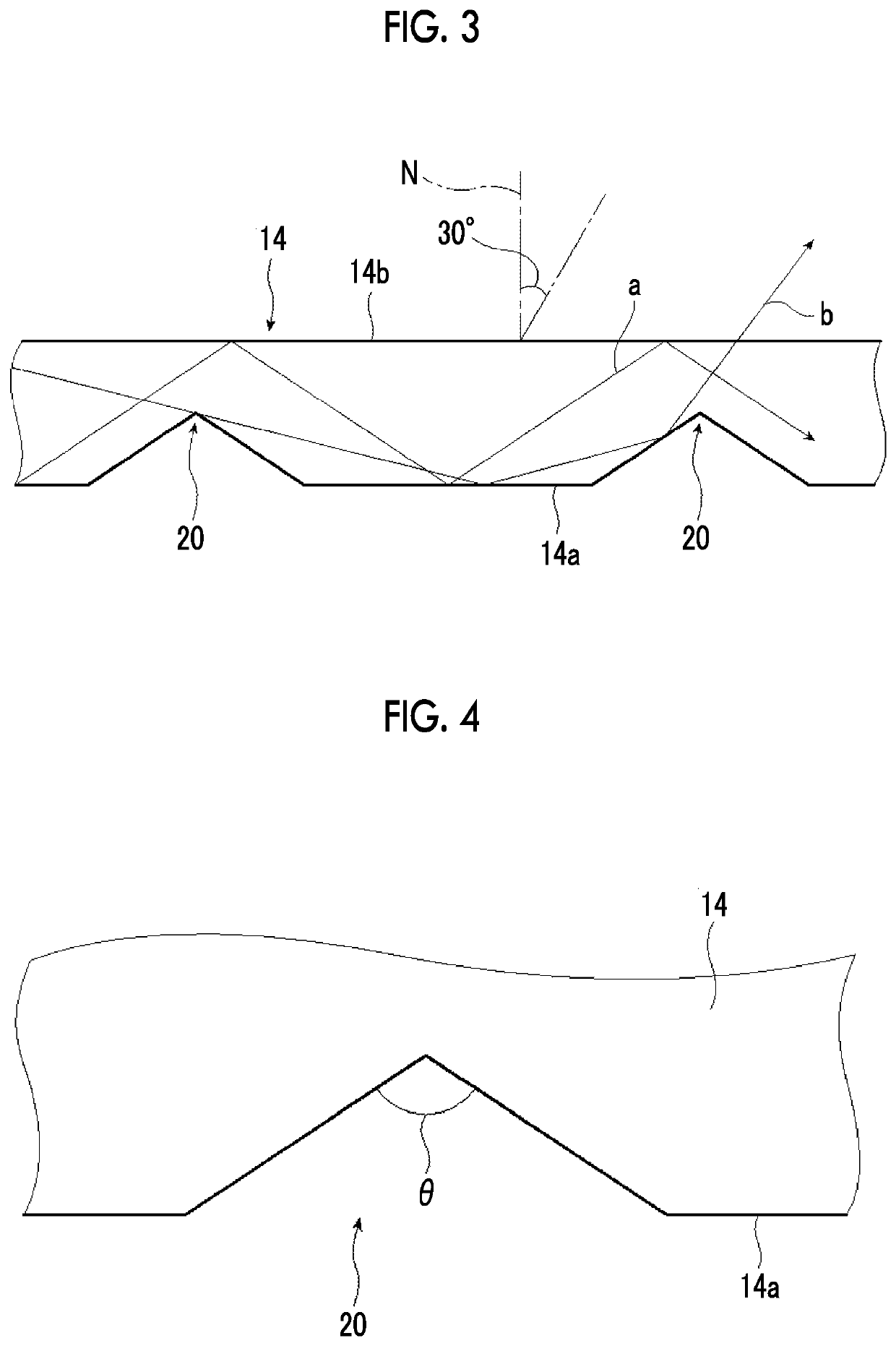
[0306]On the other hand, a mold (formed of nickel) having a plurality of long convex portions having an isosceles-triangular cross-sectional shape having an apex angle of 160° are separated from each other in a direction orthogonal to a longitudinal direction was prepared. The cross-sectional shape of the convex portion is a cross-sectional shape of the convex portion in the direction orthogonal to the longitudinal direction.
[0307]The mold was pressed to the PMMA flat plate formed for 30 minutes to transfer the shape to the flat plate. The shape was transferred in a state in which the longitudinal direction of the convex portion of the mold coincided with a transverse direction of the flat plate.
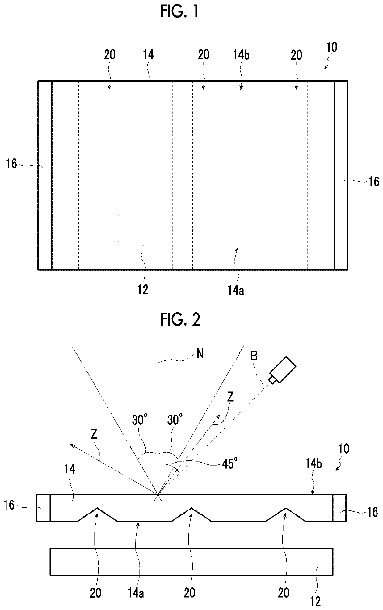
[0308]Thus, a light guiding plate as shown in FIGS. 1 and 2 in whi...
example 2
[0318]A light guiding plate was prepared and then a display device was prepared in the same manner as in Example 1 except that the apex angle of the isosceles-triangular convex portions of the mold was 150°. Accordingly, the apex angle of the long isosceles-triangular grooves of the light guiding plate of the display device is 150°.
[0319]As a result of measuring the prepared light guiding plate as in Example 1, the size s of the grooves was 20 μm, the interval p between the grooves was 100 μm, the depth of the grooves was 37 μm, and the area ratio thereof was 17% (all average values).
[0320]The proportion of obliquely emitted light was measured in the same manner as in Example 1. As a result, the proportion of obliquely emitted light was 90%.
example 3
[0321]A light guiding plate was prepared and then a display device was prepared in the same manner as in Example 1 except that the apex angle of the isosceles-triangular convex portions of the mold was 120°. Accordingly, the apex angle of the long isosceles-triangular grooves of the light guiding plate of the display device is 120°.
[0322]As a result of measuring the prepared light guiding plate as in Example 1, the size s of the grooves was 20 μm, the interval p between the grooves was 100 μm, the depth of the grooves was 17 μm, and the area ratio thereof was 17% (all average values).
[0323]The proportion of obliquely emitted light was measured in the same manner as in Example 1. As a result, the proportion of obliquely emitted light was 85%.
PUM
| Property | Measurement | Unit |
|---|---|---|
| angle | aaaaa | aaaaa |
| refractive index | aaaaa | aaaaa |
| viewing angle | aaaaa | aaaaa |
Abstract
Description
Claims
Application Information
 - R&D
- Intellectual Property
- Life Sciences
- Materials
- Tech Scout
- Unparalleled Data Quality
- Higher Quality Content
- 60% Fewer Hallucinations
Browse by: Latest US Patents, China's latest patents, Technical Efficacy Thesaurus, Application Domain, Technology Topic, Popular Technical Reports.
© 2025 PatSnap. All rights reserved.Legal|Privacy policy|Modern Slavery Act Transparency Statement|Sitemap|About US| Contact US: help@patsnap.com