Check patentability & draft patents in minutes with Patsnap Eureka AI!

Apparatuses and methods for measuring spatial properties of surface coating containing flake pigment

a technology of surface coating and flake pigment, which is applied in the direction of optical radiation measurement, instruments, spectrometry/spectrophotometry/monochromators, etc., can solve the problems of insufficient spectrophotometer for characterizing surface coatings, inability to accurately optically analyze surface coatings that are in motion, and inability to use static measurement devices

Active Publication Date: 2021-02-23
AXALTA COATING SYST IP CO LLC
View PDF22 Cites 0 Cited by
  • Summary
  • Abstract
  • Description
  • Claims
  • Application Information

AI Technical Summary

Benefits of technology

Enables accurate determination of spatial properties such as sparkle and coarseness of moving surface coatings, reducing the time and effort required for analysis and allowing for measurement of both wet and dry coatings without the need for prior curing.

Problems solved by technology

As a result, the measurements from the spectrophotometer in characterizing the surface coating are insufficient to fully characterize these materials.
However, to effectively analyze the surface coatings, static measurement with the devices is required.
More specifically, the devices are incapable of accurately optically analyzing surface coatings that are in motion, due to the impact of movement on the intensities detected by the plurality of light-sensitive sensors.
In effect, motion of the surface coating results in blurriness of the pixelated optical image provided by the optical detector, thereby negatively affecting accurate determination of intensity and intensity area correlating to the flake pigments.
It is time consuming to optically analyze immobile substrates, and it is even more time consuming to cure the surface coating prior to optically analyzing.

Method used


Image

  • Apparatuses and methods for measuring spatial properties of surface coating containing flake pigment
  • Apparatuses and methods for measuring spatial properties of surface coating containing flake pigment
  • Apparatuses and methods for measuring spatial properties of surface coating containing flake pigment

Examples


Embodiment Construction

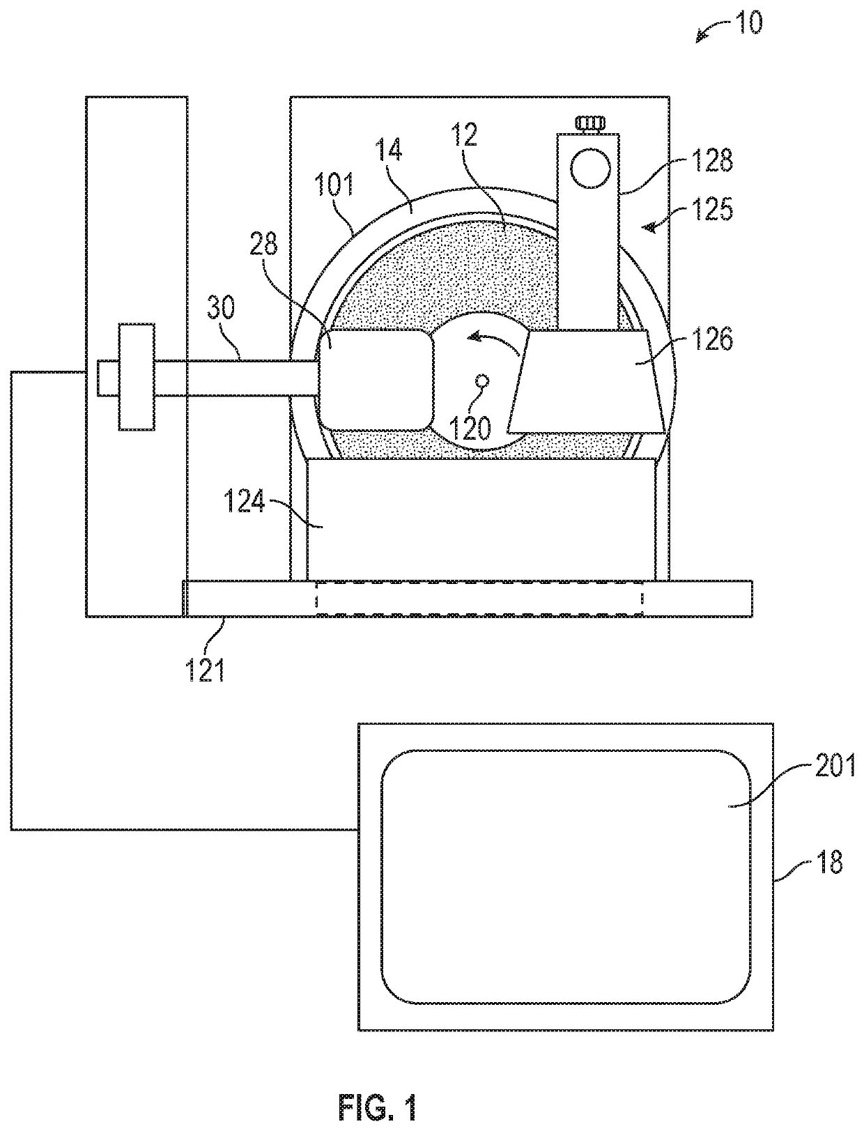
[0016]The following detailed description is merely exemplary in nature and is not intended to limit the apparatuses and methods for measuring spatial properties of a moving surface coating containing flake pigment. Furthermore, there is no intention to be bound by any theory presented in the preceding background or the following detailed description. The features and advantages of the various embodiments will be more readily understood, by those of ordinary skill in the art, from reading the following detailed description. It is to be appreciated that certain features of the subject matter disclosed herein, which are, for clarity, described above and below in the context of separate embodiments, may also be provided in combination in a single embodiment. Conversely, various features of the subject matter disclosed herein that are, for brevity, described in the context of a single embodiment, may also be provided separately or in any sub-combination. In addition, references in the si...


PUM

PropertyMeasurementUnit
distanceaaaaaaaaaa
viewing angleaaaaaaaaaa
quantum efficiencyaaaaaaaaaa

Abstract

Apparatuses and methods for measurement of spatial properties of a moving surface coating containing flake pigment are provided herein. An exemplary apparatus includes a movable surface adapted to receive the surface coating. A motion device is in mechanical communication with the movable surface. A light source provides a beam of light directed at a preselected interrogation zone through which the movable surface passes during movement thereof. A light detection device detects light reflected from the preselected interrogation zone and produces an output. A computing device is configured to determine one or more spatial properties of the surface coating based upon the output. One or more of the light source, the light detection device, or the computing device are configured to adjust for the movement of the surface coating through the preselected interrogation zone as a variable that affects measurement of reflected light by the light detection device.

Description

CROSS-REFERENCE TO RELATED APPLICATIONS[0001]This application claims the benefit of U.S. Provisional Application No. 62 / 437,707 filed Dec. 22, 2016.TECHNICAL FIELD[0002]The technical field generally relates to apparatuses and methods for measurement of spatial properties of a surface coating, and more particularly relates to apparatuses and methods for measurement of spatial properties of a surface coating that contains flake pigment.BACKGROUND[0003]Surface coatings containing a flake pigment, for example metal flake pigments such as aluminum flake, are well known. The surface coatings containing the flake pigment are particularly favored for the protection and decoration of automobile bodies, such as for example by reason of their imparting a differential light reflection effect, usually referred to as “flop”. The surface coatings containing the flake pigment also provide unique appearance effects, which include sparkle imparted by the flake as well as the enhancement of the percep...

Claims


Application Information

Patent Timeline
Patent Type & Authority Patents(United States)
IPC IPC(8): G01N21/84G01N21/55G01N33/32G01J3/50G01N1/28G01B11/30G01N21/57G01N21/47
CPCG01N21/8422G01B11/303G01J3/504G01N1/2813G01N21/55G01N33/32G01N21/57G01N2021/4769G01N2021/4771G01N2021/8427
Inventor STEENHOEK, LARRY E.GILL, HARDEEP SINGHSCHERMACHER, KEN S.
Owner AXALTA COATING SYST IP CO LLC
Features
  • R&D
  • Intellectual Property
  • Life Sciences
  • Materials
  • Tech Scout
  • Unparalleled Data Quality
  • Higher Quality Content
  • 60% Fewer Hallucinations
Learn More