
Eureka
For R&D, Eureka makes reading and utilizing patents & technical documents easy.
Eureka AIR
Designed for self-driven R&D workflows. Generate viable solutions, solve complex R&D challenges, empower your innovation with AI.

Eureka Materials
Designed for material experts only. Revolutionize your material R&D, from search, analyze, to developing new materials.

TechResearch
Generate reliable direction feasibility study reports for your R&D in just a few steps.

TechSeek
Discover and master advanced knowledge NOW. Basics, ideas, possibilities, all at once.

TechMind
As an expert in R&D Theories, TechMind can generates customized viable solutions instantly.

TechRisk
Analyze your overall solution with one click, know your potential R&D risks in advance.

TechMonitor
Get weekly tech updates, stay abreast of the latest tech innovations and key insights.
Image output device disallowing output of image data including specific image information, non-transitory storage medium storing control program and control method of image output device
a technology of image data and output device, which is applied in the direction of digital output to print units, instruments, computing, etc., can solve the problems of not being able to prevent any unauthorized printing and leaving room for image data to be output by some technology
- Summary
- Abstract
- Description
- Claims
- Application Information
AI Technical Summary
Benefits of technology
Problems solved by technology
Method used
Image

Examples
first embodiment
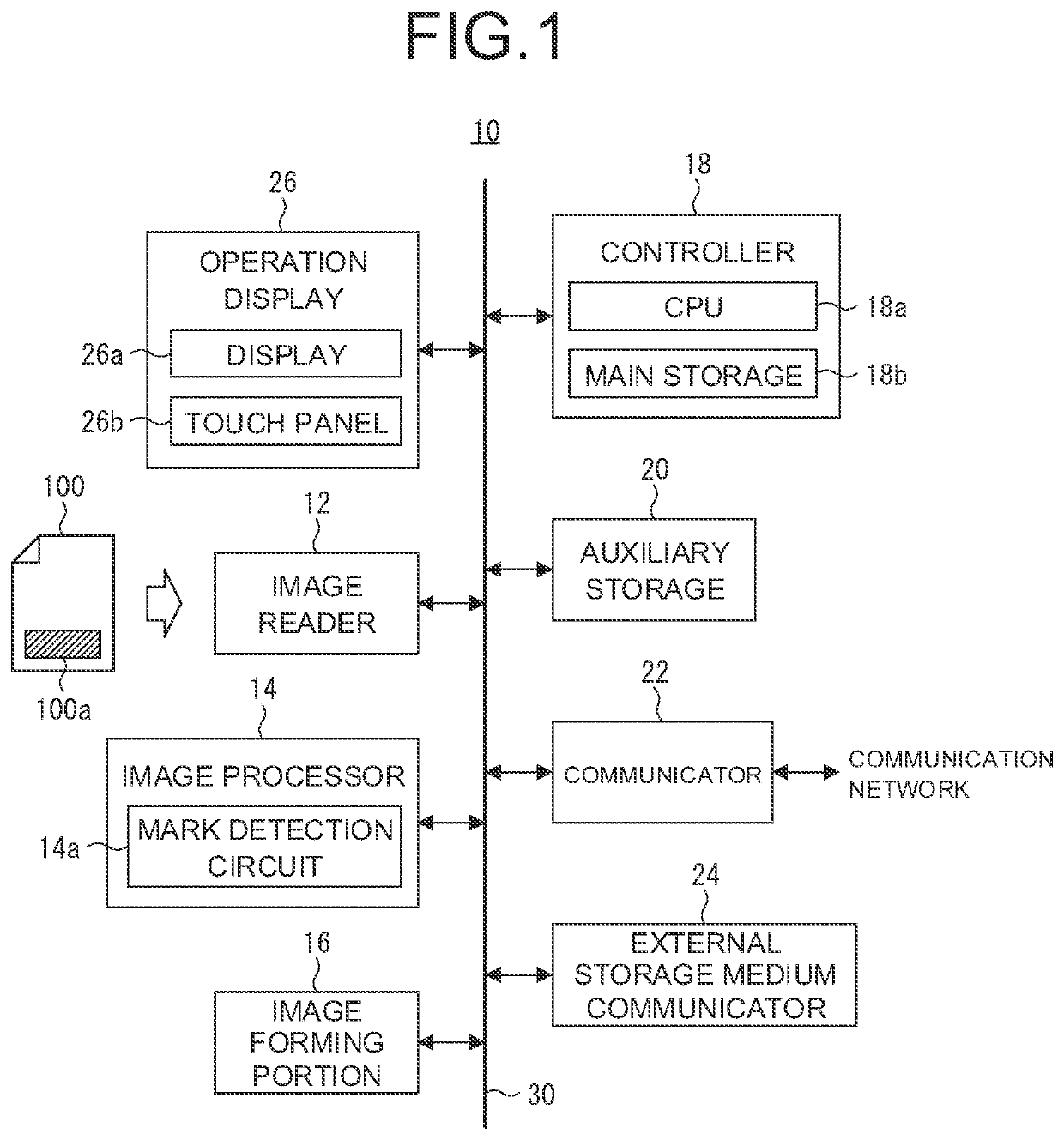
[0034]A first embodiment of the present invention will be described by taking a multifunction machine 10 shown in FIG. 1 as an example.
[0035]The multifunction machine 10 according to the first embodiment has a plurality of functions such as a copy function, a printer function, an image scanner function, and a fax function. Therefore, the multifunction machine 10 includes an image reader 12, an image processor 14, an image forming portion 16, a controller 18, an auxiliary storage 20, a communicator 22, and an external storage medium communicator 24, and an operation display 26. These are connected via a bus 30 that is common to each of the above devices.
[0036]The image reader 12 is an example of an image reader, and is a so-called document reading device. That is, the image reader 12 is responsible for an image reading processing of reading the image of a manuscript 100 and generating any two-dimensional read image data corresponding to the thus read image. In order to realize this i...
second embodiment
[0098]Next, a second embodiment of the present invention will be described.
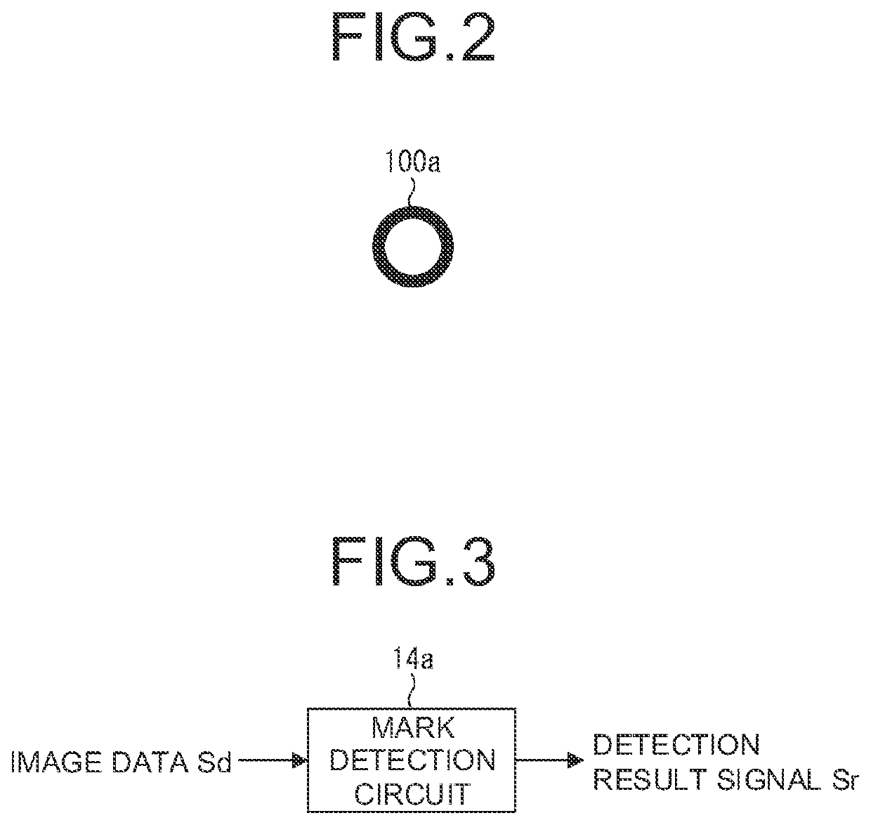
[0099]In the second embodiment, the range of the size of the copy prohibition mark 100a detectable by the mark detection circuit 14a is extended as shown in FIG. 7. That is, in the first embodiment, the range of the size of the copy prohibition mark 100a detectable by the mark detection circuit 14a, is the range of 80% to 1.25% of the original size as shown in FIG. 6. Meanwhile, the range of the size of the copy prohibition mark 100a detectable by the mark detection circuit 14a in the second embodiment is a range of 64% to 156% of the original size as shown in FIG. 7. Therefore, the mark detection circuit 14a in the second embodiment has a configuration as shown in FIG. 8.
[0100]As shown in FIG. 8, the mark detection circuit 14a according to the second embodiment has two variable magnification circuits, that is, a first variable magnification circuit 50a and a second variable magnification circuit 50b. These t...
third embodiment
[0109]Next, a third embodiment of the present invention will be described.
[0110]In the third embodiment, the range of the size of the copy prohibition mark 100a detectable by the mark detection circuit 14a is extended by a configuration different from that of the second embodiment. Specifically, the mark detection circuit 14a is configured as shown in FIG. 9.
[0111]As shown in FIG. 9, the mark detection circuit 14a in the third embodiment has two former stage buffer circuits, a first former stage buffer circuit 60a and a second former stage buffer circuit 60b. Then, the image data Sd subjected to mark detection processing is input to each of these two former stage buffer circuits 60a and 60b.
[0112]Here, the image data Sd, that is, the image data Sd input to the mark detection circuit 14a, is divided into a plurality of blocks sd, for example, N (N: integer of 2 or more), as shown in FIG. 10, in the order of being input to the mark detection circuit 14a. Then, in the first former sta...
PUM
 Abstract
Description
Claims
Application Information
 - R&D Engineer
- R&D Manager
- IP Professional
- Industry Leading Data Capabilities
- Powerful AI technology
- Patent DNA Extraction
Browse by: Latest US Patents, China's latest patents, Technical Efficacy Thesaurus, Application Domain, Technology Topic, Popular Technical Reports.
© 2024 PatSnap. All rights reserved.Legal|Privacy policy|Modern Slavery Act Transparency Statement|Sitemap|About US| Contact US: help@patsnap.com