
Fluid delivery apparatus with flow indicator and vial fill

a flow indicator and flow tube technology, applied in the direction of instruments, other medical devices, process and machine control, etc., can solve the problems of toxic reaction, inconvenient patient bed confinement, cumbersome methods,

Inactive Publication Date: 2001-11-08
PESCADERO BEACH HLDG
View PDF0 Cites 10 Cited by
  • Summary
  • Abstract
  • Description
  • Claims
  • Application Information

AI Technical Summary

Benefits of technology

[0012] It is another object of the invention to provide an apparatus of the aforementioned character which is highly reliable and easy-to-use by lay persons in a non-hospital environment.
[0013] Another object of the invention is to provide an apparatus, which can readily be filled in the field shortly prior to use.
[0014] A further object of the invention is to provide a low profile, fluid delivery device of laminate construction which can be manufactured inexpensively in large volume by automated machinery.
[0015] Another object of the invention is to provide a device of the aforementioned character which includes novel adjustable flow rate control means disposed intermediate the fluid reservoir outlet and the outlet port of the device for precisely controlling the rate of fluid flow from the outlet port toward the patient.
[0016] Another object of the invention is to provide a device of the character described which embodies a highly novel fluid flow indicator that provides a readily discernible visual indication of fluid flow status through the device.
[0020] Another object of the present invention is to provide an apparatus that includes novel means for preventing the unauthorized manipulation of the priming mechanism of the device.

Problems solved by technology

Certain classes of new pharmacologic agents possess a very narrow range of therapeutic effectiveness, for instance, too small a dose results in no effect, while too great a dose results in toxic reaction.
Such methods are cumbersome, imprecise and require bed confinement of the patient.
The prior art bladder type infusion devices are not without drawbacks.
Generally, because of the very nature of the bladder or "balloon" configuration, the devices are unwieldy and are difficult and expensive to manufacture and use.
Further, the devices are somewhat unreliable and their fluid discharge rates are frequently imprecise.

Method used


Image

  • Fluid delivery apparatus with flow indicator and vial fill
  • Fluid delivery apparatus with flow indicator and vial fill
  • Fluid delivery apparatus with flow indicator and vial fill

Examples


Embodiment Construction

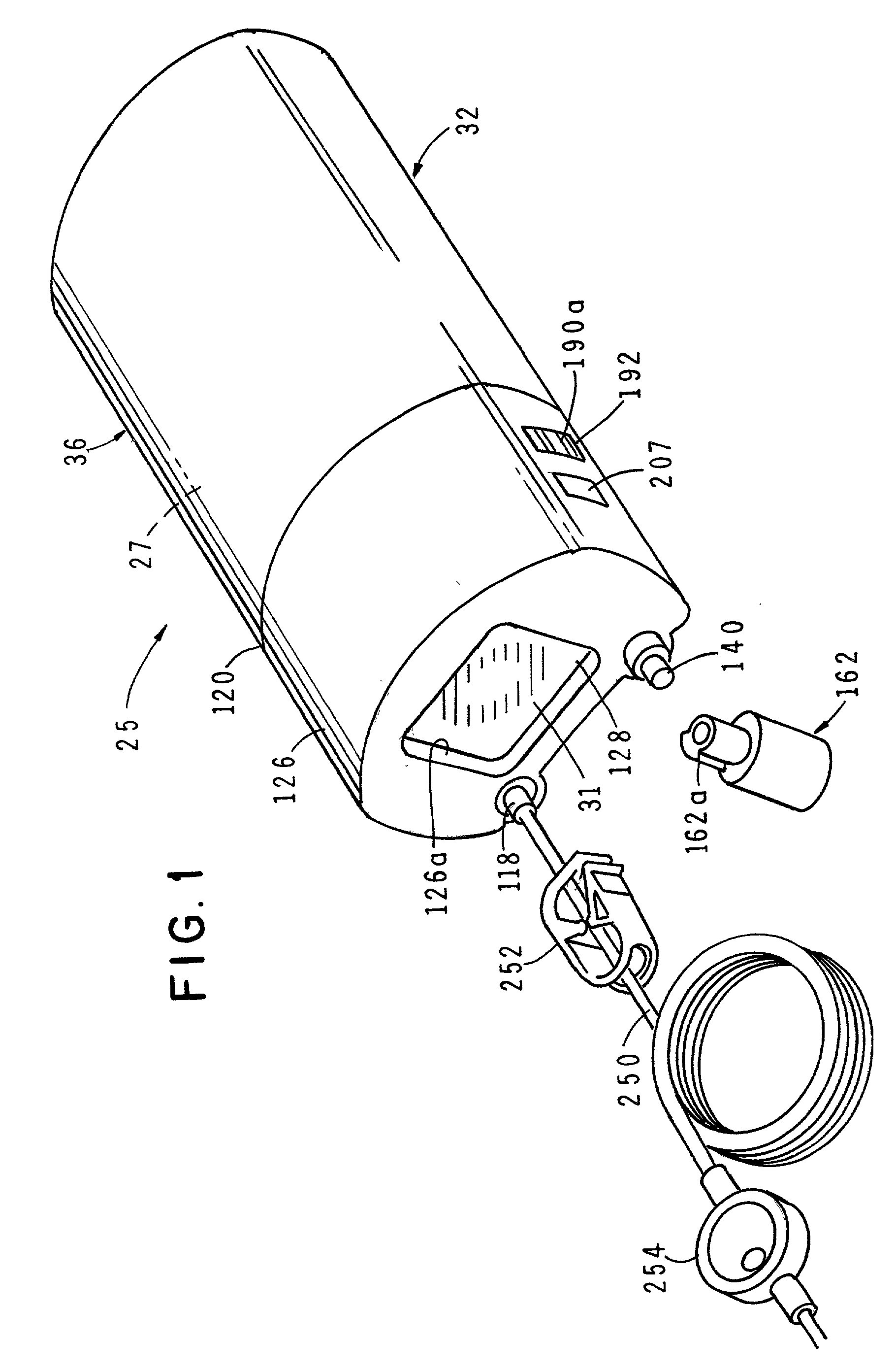
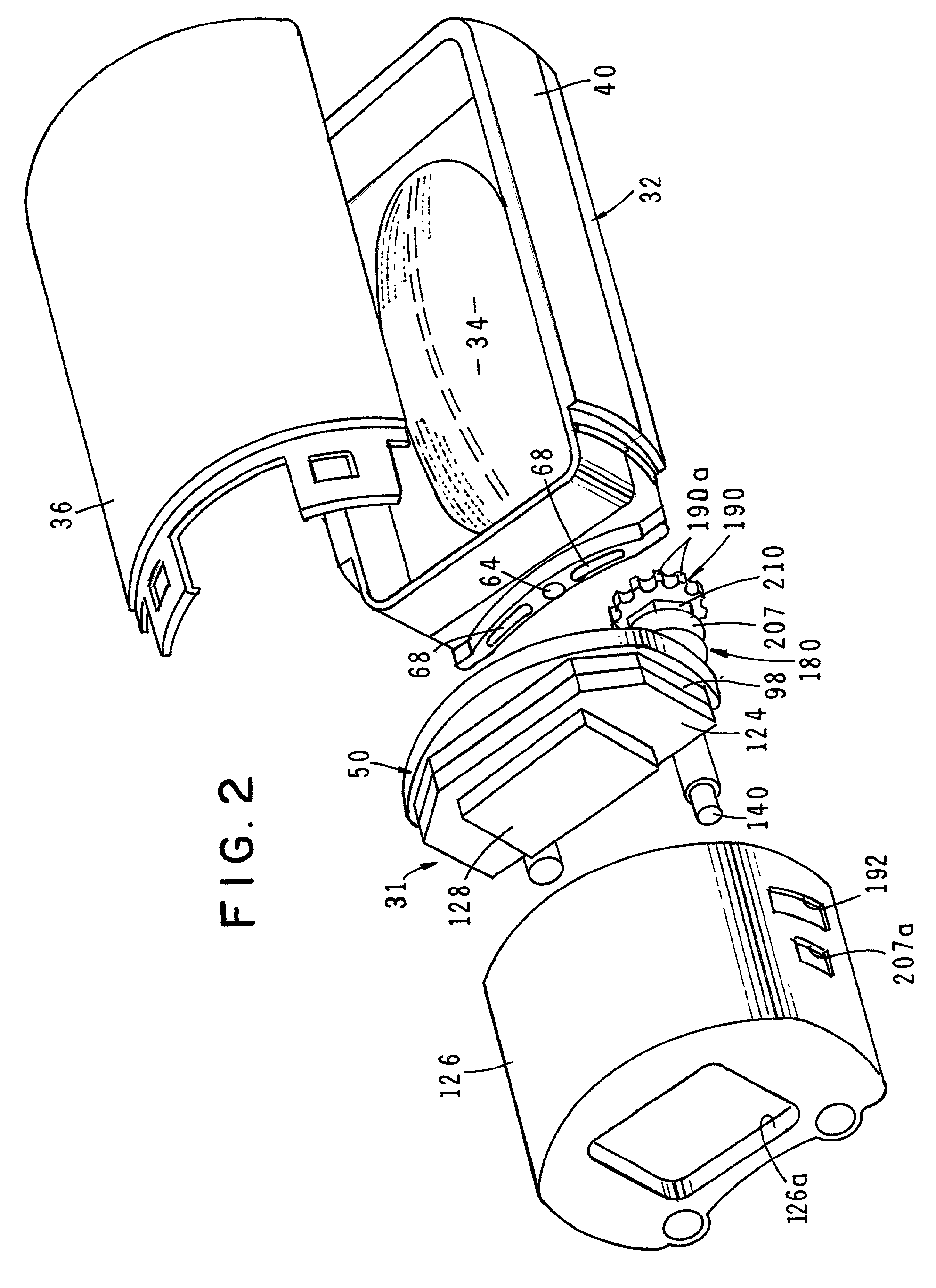
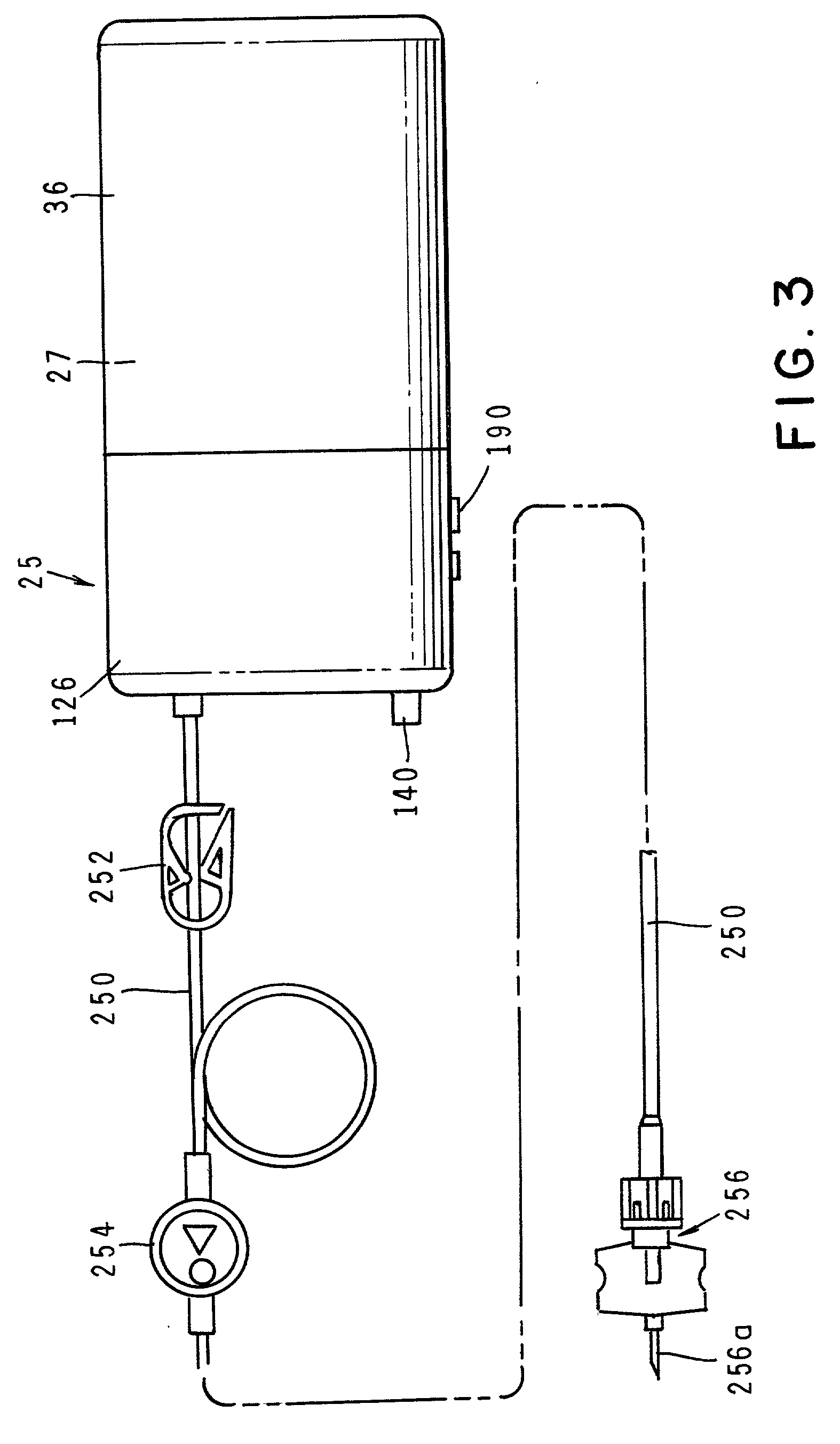
[0065] Referring to the drawings and particularly to FIGS. 1 through 4, one form of the apparatus of the invention is there illustrated and generally designated by the numeral 25. The apparatus is somewhat similar to that shown in FIGS. 26 through 37 of incorporated-by-reference Ser. No. 09 / 165,706 and comprises five major cooperating subassemblies namely, a reservoir subassembly 27, an adjustable flow rate control subassembly 29 (FIG. 4), a flow indicator subassembly 31, fill means for filling the fluid reservoir of the reservoir subassembly and infusion means for delivering the medicinal fluid to the patient.

[0066] Considering first the reservoir subassembly, the details of which are best seen in FIG. 4, this subassembly includes a base assembly 32, a stored energy source, shown here as a distendable membrane 34, and a cover 36 for enclosing the stored energy source. The base assembly includes an ullage substrate 38 and a membrane capture housing 40 having a bottom opening 42 whic...


PUM


Abstract

An apparatus for accurately infusing medicinal agents into an ambulatory patient at specific rates over extended periods of time. The apparatus includes a housing having a delivery outlet and an elastic distendable membrane for defining a chamber within the housing. Also provided is a flow rate control assembly delivery outlet. The apparatus further includes a mechanism for quickly and easily priming the fluid flow passageways of the fluid delivery component. Additionally, the apparatus includes a novel fluid flow indicator that provides a readily discernible visible indication of fluid flow through the apparatus. Further provided is a fill assembly for filling the fluid reservoir of the device with a selected medicinal fluid and locking mechanisms for preventing unauthorized tampering with the flow rate control mechanism as well as the priming mechanism.

Description

[0001] This is a Continuation-In-Part of co-pending U.S. application Ser. No. 09 / 165,706 filed Oct. 2, 1998 which is a Continuation-In-Part of U.S. application Ser. No. 08 / 768,663 filed Dec. 18, 1996.[0002] 1. Field of the Invention[0003] The present invention relates generally to fluid delivery devices. More particularly, the invention concerns an improved apparatus for infusing medicinal agents into an ambulatory patient at specific rates over extended periods of time, which apparatus includes fluid flow indicator means and a novel adjustable flow rate control means for precisely adjustably controlling the rate of fluid flow from the reservoir of the device and means for priming the device to fill the fluid passageways thereof prior to commencing the delivery step.[0004] 2. Discussion of the Prior Art[0005] Many medicinal agents require an intravenous route for administration thus bypassing the digestive system and precluding degradation by the catalytic enzymes in the digestive t...

Claims


Application Information

Patent Timeline
Patent Type & Authority Applications(United States)
IPC IPC(8): A61M5/14A61M5/152A61M5/168
CPCA61M2205/585A61M5/141A61M5/152A61M5/16877A61M2205/583
Inventor KRIESELL, MARSHALL S.THOMPSON, THOMAS N.ARNOLD, STEVEN M.GARRISON, JAMESHOGAN, ROLFKAZEMZADEH, FARHADKUESTER, WILLIAM
Owner PESCADERO BEACH HLDG
Learn More