Small-sized tiller

Active Publication Date: 2010-05-27
HONDA MOTOR CO LTD
View PDF6 Cites 6 Cited by
  • Summary
  • Abstract
  • Description
  • Claims
  • Application Information

AI Technical Summary

Benefits of technology

[0014]The box-like carrier case may further have at least one drain hole formed in a front wall or a rear wall of the box-like carrier case for drawing off water from the carrier case. The drain hole is preferably located at a position vertically and upwardly separated from a bottom wall of the carrier case by a predetermined distance. Since the drain hole is located at a higher level than that of the bottom wall of the carrier case, the carrier case can retain a predetermined amount of water that may drop fr

Problems solved by technology

However, since the kickstand requires a separate bracket for attachment to the body frame, the tiller having such kickstand becomes relatively complicated in construction and costly to manufacture.
Furthermore, since the tilling unit itself forms a part of the stand unit, the tiller is practica

Method used


Image

  • Small-sized tiller
  • Small-sized tiller
  • Small-sized tiller

Examples


Example

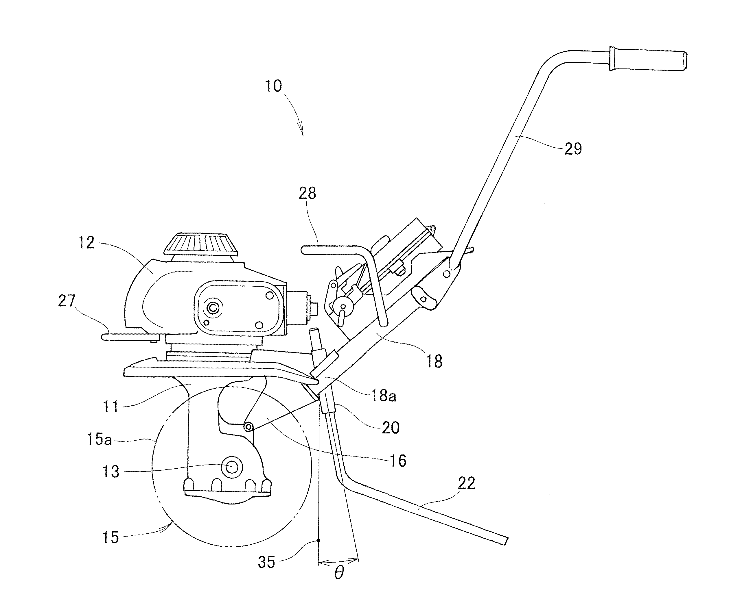
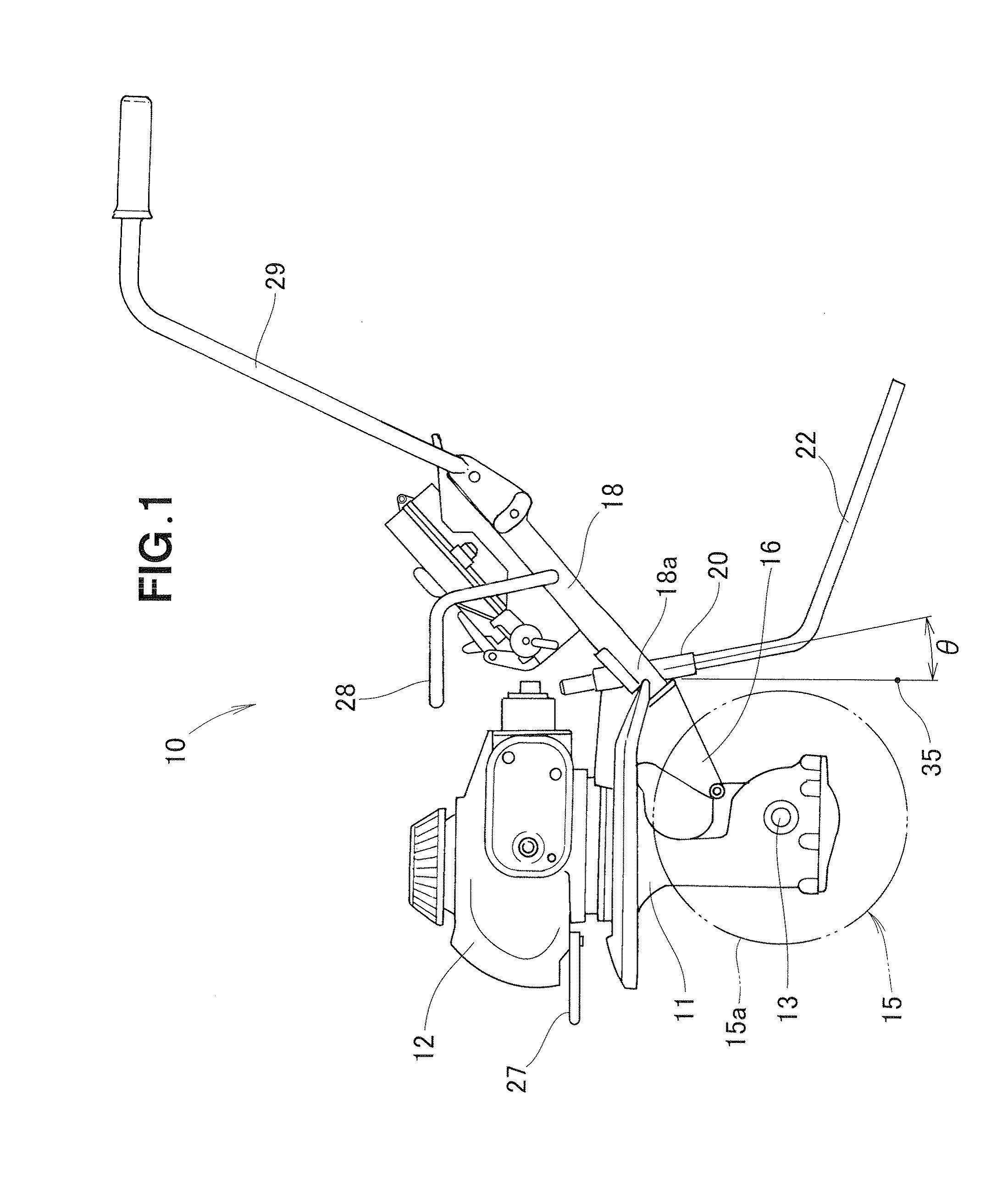
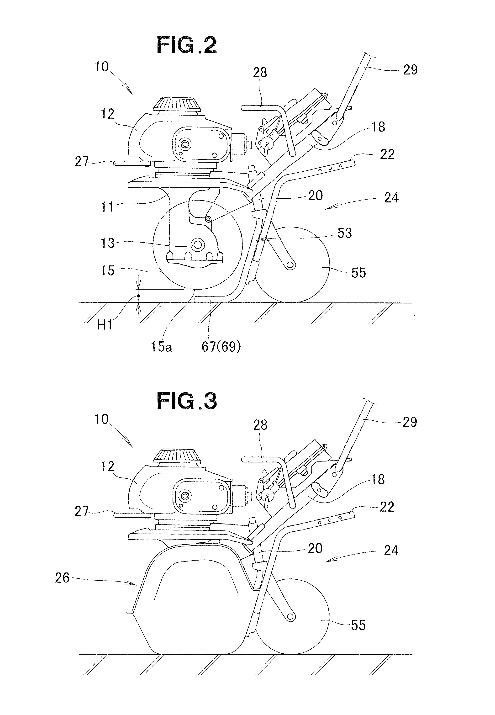
[0029]Referring now to the drawings and FIG. 1 in particular, there is shown a small-sized tiller 10 according to one preferred embodiment of the present invention. The tiller 10 takes the form of a walk-behind tiller and generally comprises a body frame 11, an engine 12 mounted on an upper end of the body frame 11, a horizontal tilling shaft 13 rotatably mounted on a lower portion of the body frame 11, a tilling unit (cultivating tool) 15 removably mounted to the tilling shaft 13 for rotation with the shaft 13 and having a plurality of tilling tines 15a (FIG. 11), a handle column 18 mounted via a bracket 16 to a rear part of the body frame 11 and extending obliquely upward in a rearward direction of the body frame 11, a resistance-bar attachment portion 20 connected to a front end portion of the handle column 18, a resistance bar 22 removably mounted to the resistance-bar attachment portion 20, a carry handle 28 provided on an intermediate portion of the handle column 18, and an op...


PUM


Abstract

A small-sized tiller includes a stand unit configured to solely support the tiller in a self-standing state. The stand unit has a pole portion removably mountable to a resistance-bar attachment portion of the body frame when a resistance bar has been removed from the resistance-bar attachment portion.

Description

FIELD OF THE INVENTION[0001]The present invention relates to a small-sized tiller having a resistance bar removably mounted in an attachment hole in the body frame for insertion into the ground to stabilize the posture of the tiller during tilling operation.BACKGROUND OF THE INVENTION[0002]Various small-sized tillers of the type concerned are known and used heretofore. According to one example of such known small-sized tillers, which is disclosed in Japanese Patent Laid-open Publication (JP-A) No. 2006-115777, a kickstand provided at a front portion of the body frame flips down from the body frame and makes contact with the ground to allow the tiller to be kept upright in a condition in which the kickstand, tilling tines of a tilling unit, and a resistance bar are in contact with the ground. In the disclosed tiller, the stand, tilling unit and resistance bar together form a stand unit.[0003]However, since the kickstand requires a separate bracket for attachment to the body frame, th...

Claims


Application Information

Patent Timeline
IPC IPC(8): A01B33/16A01B33/00A01B63/00
CPCA01B33/028A01B33/08A01B33/16A01B76/00
Inventor ITO, TOMOKIAZUMA, KOICHINAKAYA, TOMOMISASAOKA, MASAYUKI
Owner HONDA MOTOR CO LTD
Why Eureka
Try Eureka