Liquid-level gauge

a liquid level gauge and gauge technology, applied in the direction of level indicators with buoyant probes, instruments, optical radiation measurement, etc., can solve the problems of increasing the scale of the gauge, increasing the number of parts, and complicated structure, so as to increase the strain generated in the optical fiber, increase the buoyancy acting, and accurately proportional to the change in the strain of the optical fiber.

Inactive Publication Date: 2002-09-19
NTT ADVANCED TECH
View PDF0 Cites 11 Cited by
  • Summary
  • Abstract
  • Description
  • Claims
  • Application Information

AI Technical Summary

Benefits of technology

0016] In the first to eighth inventions, when the liquid-level height changes, the magnitude of buoyancy either the float or the suspension member receives from liquid also changes. Since the cross-sectional area of the float or suspension member is uniform in the longitudinal direction, the value of a change in liquid-level height is accurately proportional to a change in the buoyancy acting on the float or suspension member. Also, a change in strain in the optical fiber is accurately proportional to the change in the buoyancy. In the case of the float, as the liquid-level height rises to increase the buoyancy acting on the float, the optical fiber or wire supporting the float is tensed. Accordingly, tension applied to the optical fiber or wire increases in proportion to the buoyancy to increase strain generated in the optical fiber. In the case of the suspension member, as the liquid-level height rises to increase the buoyancy acting on the suspension member, tension applied to the wire suspending the suspension member decreases in inverse proportion to an increase in the buoyancy to thereby decrease strain generated in the optical fiber. Accordingly, by detecting strain generated in the optical fiber in accordance with a change in buoyancy by means of the optical fiber strain gauge, a liquid-level height can be measured accurately from the correlation between the liquid-level height and the buoyancy.
0017] In the first to fourth inventions, the support portion of optical fiber is turned round or looped so that it

Problems solved by technology

In the conventional liquid-level gauge, especially, the float type liquid-level gauge using a magnet and a plurality of reed switches, however, it is necessary that the magnet be built in the float and a great number of reed switches be incorporated in guide pipes for guiding the float, raising a problem that the number of parts increases and the s

Method used


Image

  • Liquid-level gauge
  • Liquid-level gauge
  • Liquid-level gauge

Examples


first embodiment

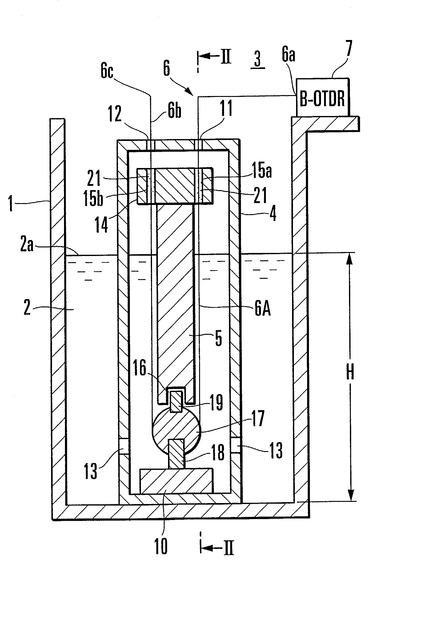
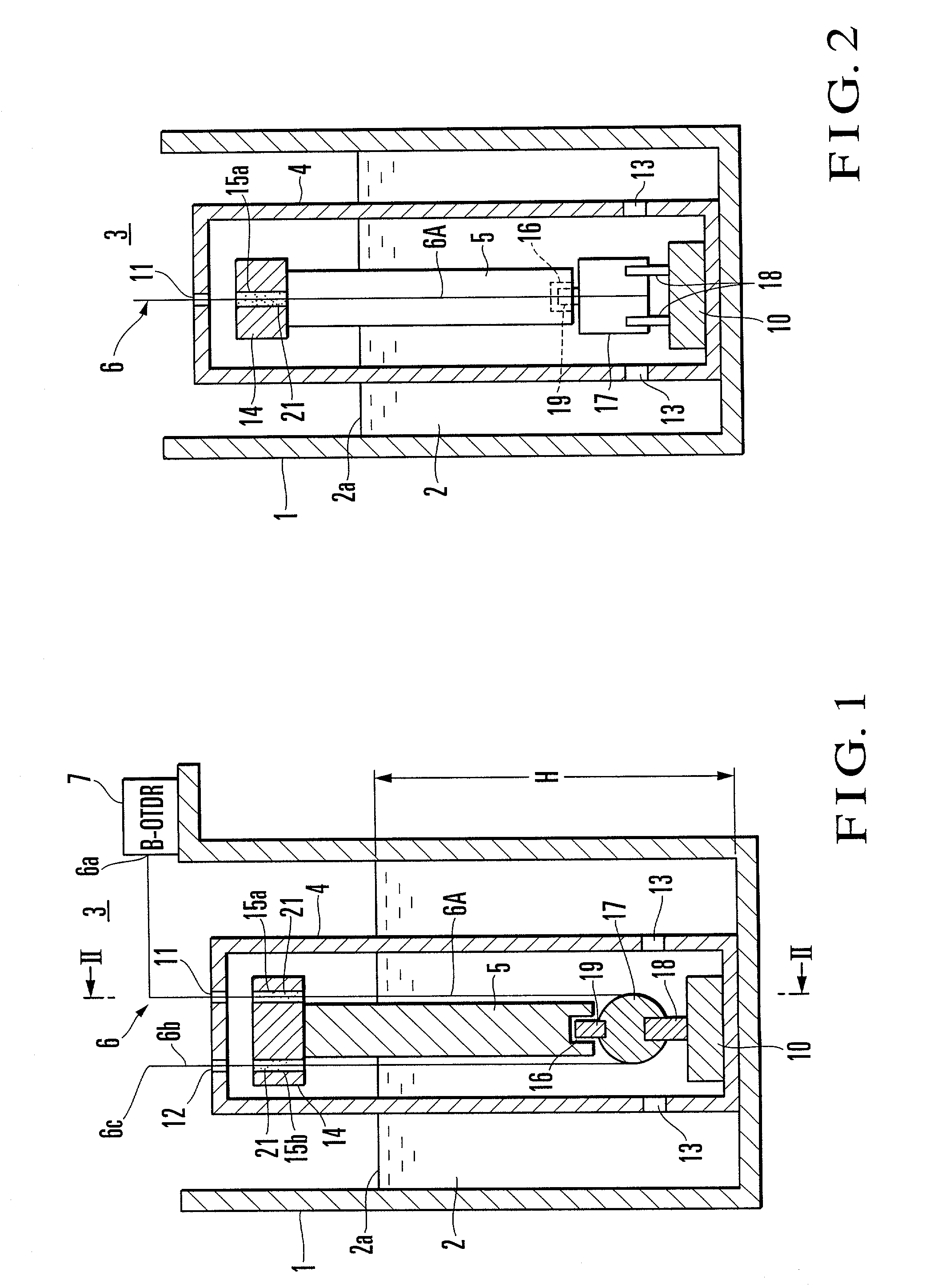
[0034] Referring first to FIG. 1, a float type liquid-level gauge of the invention is illustrated in sectional form. FIG. 1 is sectioned on line II-II as shown in FIG. 2. In these figures, an open vessel 1 stores liquid 2 representing an object to be measured and a liquid-level gauge 3 is adapted to measure a height of liquid level 2a (liquid-level height) of the liquid 2.

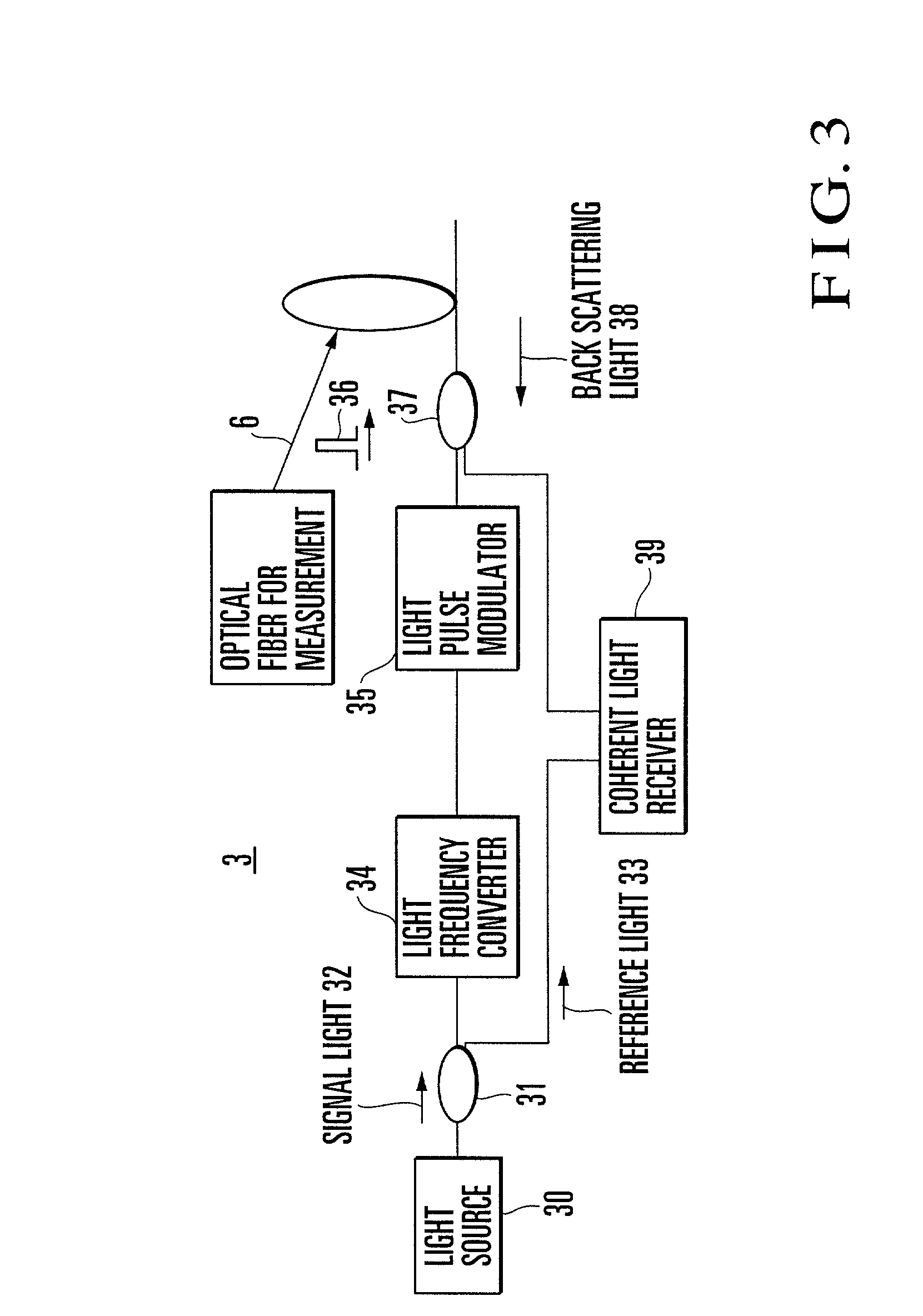
[0035] The liquid-level gauge 3 comprises a sleeve 4 arranged in the vessel 1, a float 5 dipped in the liquid 2 inside the sleeve 4, an optical fiber 6 supporting the float 5 to keep it at a constant height, and an optical fiber strain gauge 7, as represented by a Brillouin-optical time domain reflectometer (B-OTDR), disposed on the vessel.

[0036] The sleeve 4 takes a cylindrical form having its top end protruding upwardly of the liquid 2 and its lower bottom end fixed to the bottom of the vessel 1 by means of a fixing member 10. The interior of the sleeve 4 is opened to atmosphere through two holes 11 and 12 for fi...

second embodiment

[0055] Referring to FIG. 4, the float type liquid-level gauge of the invention is illustrated in sectional form. FIG. 5 is a longitudinal sectional diagram taken on line V-V of FIG. 4.

[0056] In the present embodiment, a strain detector 6A of optical fiber 6 is turned round three times between two fiber support members 14 and 17. Accordingly, the upper fiber support member 14 is made to be columnar like the lower fiber support member 17 and is disposed horizontally on the top surface of a float 5, so that the optical fiber 6 can be turned round on the upper side. The other structure is the same as that of the aforementioned first embodiment and therefore, identical components to those in the first embodiment are designated by identical reference numerals and will not be described herein.

[0057] With the construction as above, the apparent length of the strain detector 6A can be shortened by the number of turn-round operations to bring about advantages that the gauge can further be red...

third embodiment

[0058] Referring to FIG. 6, the float type liquid-level gauge of the invention is illustrated in sectional form. FIG. 7 is a longitudinal sectional view taken on line VII-VII of FIG. 6.

[0059] In the present embodiment, fiber fixing pipes 15a and 15b for fixing the opposite ends of a strain detector 6A of optical fiber 6 are provided for a lower fiber support member 17 and the strain detector 6A is turned round three times between the lower fiber support member 17 and an upper fiber support member 14. The upper fiber support member 14 is made to be columnar and disposed horizontally on the top surface of a float 5, having a recess 41 formed in its upper surface, and a boss 42 provided to a sleeve 4 engages the recess 41 to cooperates with a lower boss 19 for the sake of preventing the float 5 from falling down.

[0060] Obviously, with the structure as above, too, the same effects as those in the second embodiment can be obtained.


PUM


Abstract

There is provided a liquid-level gauge for accurately measuring a liquid-level height of fluid to be measured. In the liquid-level gauge, a float having a uniform cross-sectional form in the height direction and a specific weight value small than that of liquid is dipped in the liquid. The float is supported by an optical fiber at a constant height such that its upper end always projects from the liquid level. One end of the optical fiber is connected to an optical fiber strain gauge and a strain detector is turned round between fiber support members. When the float receives buoyancy from the liquid, tension is applied to the strain detector of optical fiber to generate strain therein. By detecting the strain by means of an optical fiber strain gauge, a liquid-level height can be measured.

Description

BACKGROUND OF THE INVENTION[0001] The present invention relates to a liquid-level gauge for measuring a height of liquid level and more particularly, to a liquid-level gauge for measuring a liquid-level height by generating strain in an optical fiber by the action of vertically upward force a body dipped in liquid receives from the liquid (buoyancy) and measuring the strain.[0002] Liquid-level gauges for measurement of a height of liquid level based on various principles have hitherto been proposed. For example, an electrostatic capacitance type liquid-level gauge (JP-A-2000-097750 or JP-A-11030544), a barometric liquid-level gauge (JP-A-2000-088629), a float type liquid-level gauge (JP-A-10-148565 or JP-A-11-326015), an electrode type liquid-level gauge (JP-A-11-023346) and an electric wave type liquid-level gauge (JP-A-10-197617) have been known. Specifically, the present invention provides a float type or comparable type liquid-level gauge, especially, using an optical fiber.[000...

Claims


Application Information

Patent Timeline
IPC IPC(8): G01F23/40G01F23/22G01F23/68G01F23/76
CPCG01F23/686G01F23/76G01F23/0038
Inventor YASHIRO, TAKAMASAMOCHIZUKI, SATOSHIYOSHITOMI, TAKAHARU
Owner NTT ADVANCED TECH
Why Eureka
Try Eureka