Surface light source device, display and light guide plate

Inactive Publication Date: 2003-01-09
ENPLAS
View PDF0 Cites 16 Cited by
  • Summary
  • Abstract
  • Description
  • Claims
  • Application Information

AI Technical Summary

Benefits of technology

0027] This feature enables to the light guide plate to provide a high-brightness region in correspondence to said particular partial region when light is inputted on into the light guide plate.
0028] Typicall

Problems solved by technology

If such uneven brightness is not reduced, the image display unit illuminated by the surface light source device provides an uneven image brightness, leading to undesirable visual effects.
In recent years, however, such uniform brightness over an emission face does not always give the best condition.

Method used


Image

  • Surface light source device, display and light guide plate
  • Surface light source device, display and light guide plate
  • Surface light source device, display and light guide plate

Examples


first embodiment

[0045] First Embodiment;

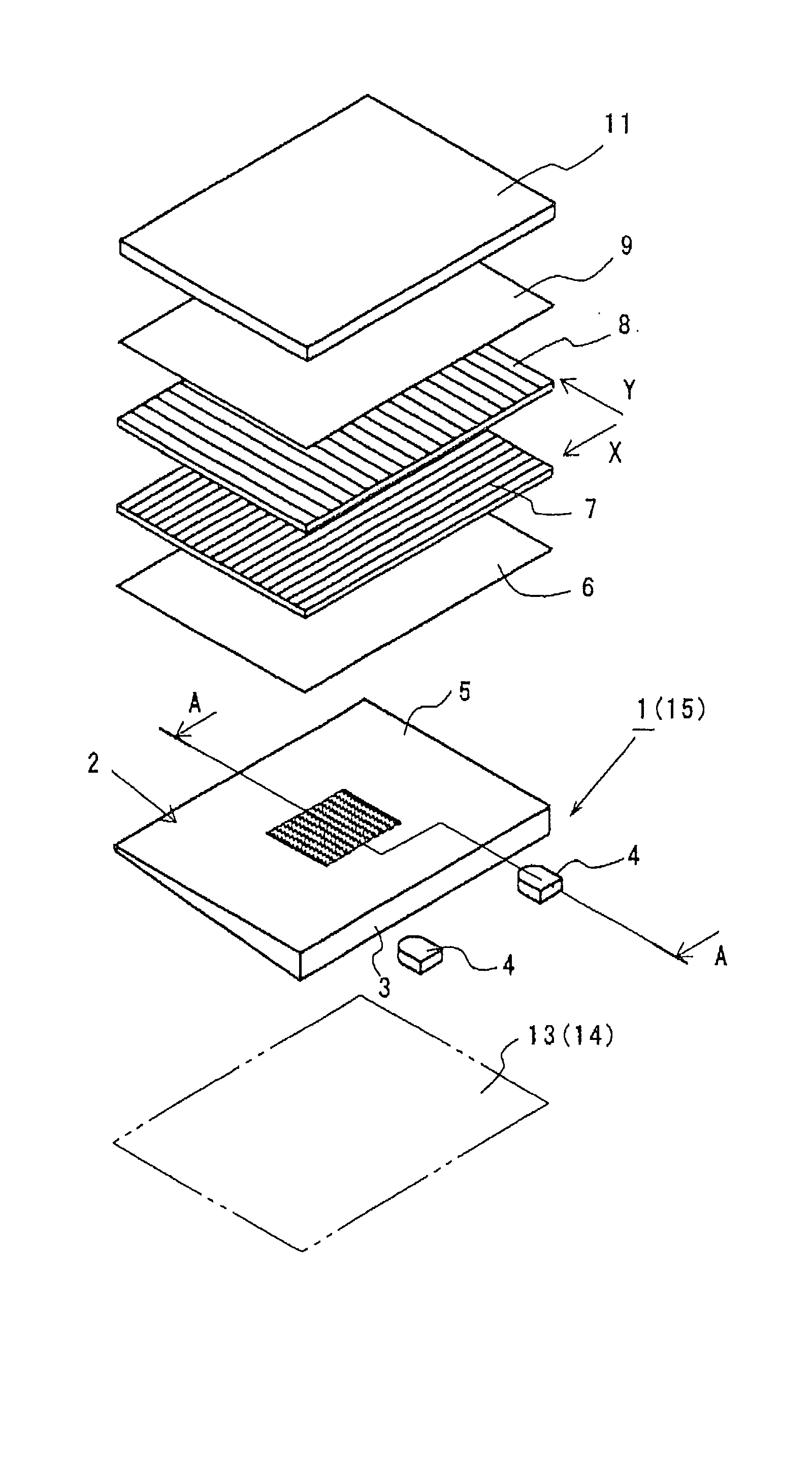
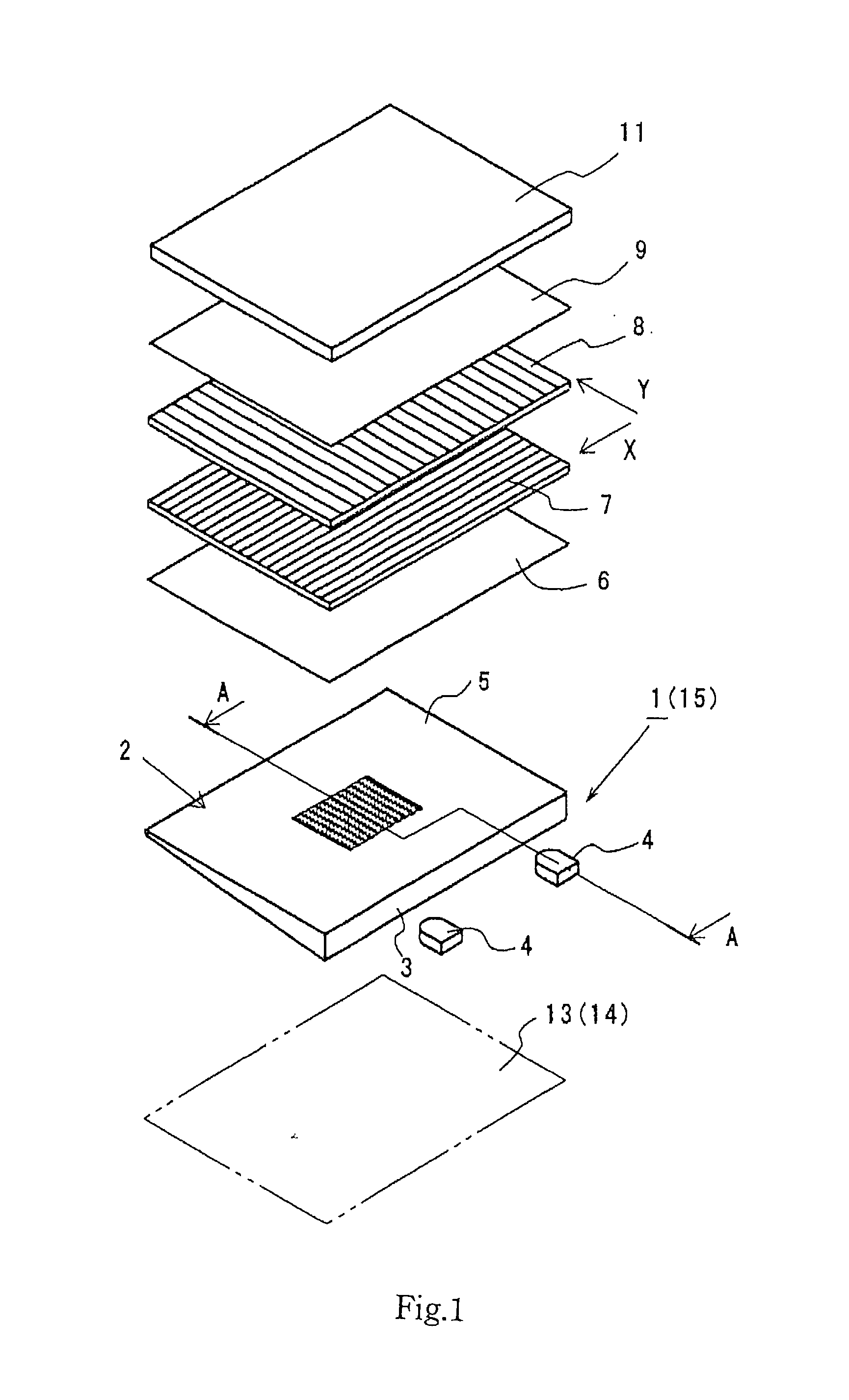
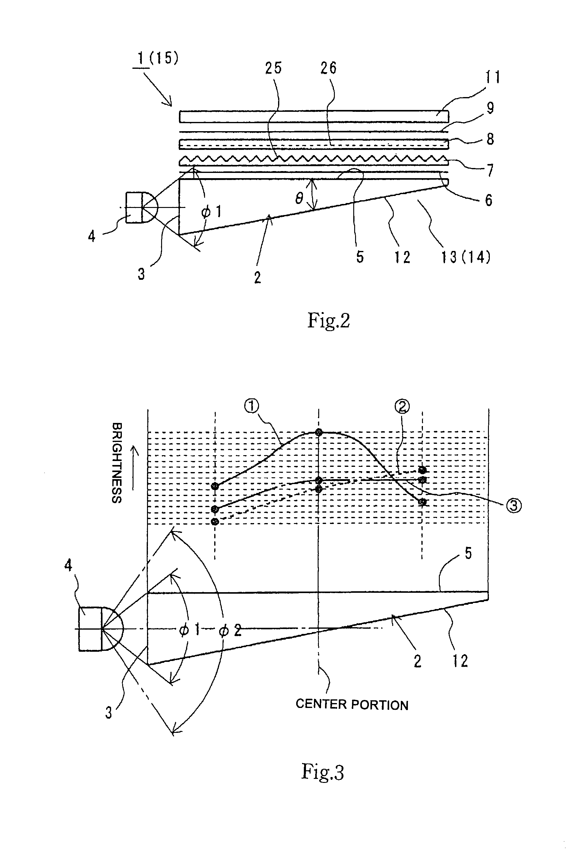
[0046] FIGS. 1 and 2 illustrate a display of the first embodiment in accordance with the present invention. The display is a liquid crystal display 1 a perspective view of which is shown in FIG. 1. FIG. 2 is a cross section along line A-A in FIG. 1.

[0047]

[0048] Referring to FIGS. 1 and 2, the LCD 1 comprises a light guide plate 2, light emitting diode 4 as primary light source, first through forth light control member 6 to 9 and liquid crystal display panel 11 as image display unit.

[0049] The LED 4 is disposed near to an incidence face 3 of the light guide plate 2 and the light control members 6 to 9 are piled and arranged along an emission face 5 of the light guide plate 2. The LCD panel 11 is disposed outside of the forth light control member 9.

[0050] Further, a member having a superior reflectivity (such as reflection sheet 13 or reflection face 14 of a casing) is arranged along a back face 12 (opposite with the emission face 5) of the light guide plate 2...

second embodiment

[0121] Second Embodiment;

[0122] FIG. 12 illustrates an emission face 5 of a light guide plate 2 employed in the second embodiment in accordance with the present invention. As shown in FIG. 12, the second light diffusion pattern 19 is formed only in an approximately center portion of the emission face 5.

[0123] This brings a clearer appearing emission brightness difference between the approximately center portion of the emission face 5 and the rest portion.

third embodiment

[0124] Third Embodiment;

[0125] FIG. 13 illustrates an emission face 5 of a light guide plate 2 employed in the third embodiment in accordance with the present invention.

[0126] As shown in FIG. 13, one or more second light diffusion patterns 19 are formed in one or more particular partial regions 29. This enables each of these particular regions to have a heightened emission brightness as compared with the rest region. The LCD panel displays an brighter image, corresponding to each of the particular regions, as compared with the rest area.

[0127] This embodiment is suitable for cases where a LCD panel is divided into a plurality of screen areas which provide digital images differently from each other. If the instant embodiment is applied to the cases, each of the divided screen areas are illuminated by highly bright light, bringing images easy to observe.

[0128] Forth Embodiment;

[0129] FIG. 14 illustrates a light guide plate 2 employed in the forth embodiment in accordance with the pre...


PUM


Abstract

A light guide plate has a back face provided with a first light diffusion pattern which tends to get denser according to an increasing distance from a primary light source. The light guide plate has an emission face provided with a second light diffusion pattern covering rate of is the largest at an approximately center portion (particular partial region) of the emission face. The first and second light diffusion patterns consist of a great number of fine light diffusion elements, respectively. Each fine light diffusion element of the second light diffusion pattern has a smaller size as compared with that of the first light diffusion pattern. The emission face of the light guide plate has an effective emission area to provide an emission light which is supplied to an LCD panel or other objects to be illuminated, via a light control member such as prism sheet. The approximately center portion and / or other one or more particular partial regions in the emission face show an intentionally heightened brightness. This enables an image display unit to have an approximately center portion and / or other one or more particular partial regions which display a brightness-emphasized image. Such an emphasis display technique is suitably applied to devices such as digital still cameras or digital video cameras which employ image-screen-center-portion focusing.square

Description

[0001] 1. Field of Invention[0002] The present invention relates to a surface light source device generating a light flux illuminating an image display unit, such as LCD panel, of a display and to a display, such as LCD, which employs the surface light source device. The present invention also relates to a light guide plate which is employed in the surface light source device or display.[0003] 2. Related Art[0004] It has been well known that a display for digital still cameras, digital video cameras, portable telephones, electronic pocket notebooks, car navigation devices, portable personal computers or liquid crystal television sets comprises an image display unit, such as LCD panel, illuminated by a surface light source device.[0005] In general, a surface light source device comprises a primary light source such as fluorescent lamp or LED and a light guide plate having a side face (incidence face) through which the light guide plate is supplied with light of the primary light sour...

Claims


Application Information

Patent Timeline
IPC IPC(8): G02B6/00F21V8/00F21Y101/02G02F1/13357
CPCG02B6/002G02B6/003G02B6/0036G02B6/0046G02B6/0058G02B6/0061
Inventor SUZUKIOHSUMI, KAZUMASA
Owner ENPLAS
Why Eureka
Try Eureka