Exposure head, exposure apparatus, and application thereof

Active Publication Date: 2005-05-17
FUJIFILM HLDG CORP +1
View PDF19 Cites 16 Cited by
  • Summary
  • Abstract
  • Description
  • Claims
  • Application Information

AI Technical Summary

Benefits of technology

[0094]For the incorporated laser light source, it is preferable to use the optical fiber, in which the core diameter is uniform and the clad diameter of the outgoing end is smaller that that of the incident end. The high brightness of the light source can be achieved by decreasing the clad diameter of the outgoing end. Considering that the diameter of the light-emitting point is decreased, it is preferable that the clad diameter of the outgoing end of the optical fiber is less than 125 μm, in view of the smaller diameter of the light-emitting point, it is more preferable that the clad diameter of the outgoing end is not more than 80 μm, and it is particularly preferable that the clad diameter of the outgoing end is not more than 60 μm. The optical fiber in which the core diameter is uniform and the clad diameter of the outgoing end is smaller that that of the incident end can be formed, e.g., by coupling the plurality of optical fiber in which the core diameters are the same and the clad diameters are different. This enables the light-emitting area to be further decreased when the optical fibers are arrayed

Problems solved by technology

That is to say, there is a problem that modulation speed of DMD is slow, so that it is difficult to perform the high-speed exposure in the exposure head using DMD as the spatial light modulator.
However, in the rapid prototyping apparatus adopting the laser plotter method, there is the problem that shutter speed and moving speed of the plotter are limited and plenty time is required for the shaping.
However, in the rapid prototyping apparatus adopting the movable mirror method, since the scanning is performed with a micro laser spot, the shaping requires for long hours, for example, even in the case that the fast scanning of 2 to 12 m/s is performed, it takes 8 to 24 hours to shape the three-dimensional model of about 10 centimeter cubic.
When rotating angle of the Y-axis rotating mirror 274 is increased, though the irradiation area is enlarged, the positioning accuracy is worsened in similar way, and a pin cushion error is increased.
Furthermore, in the rapid prototyping apparatus using the galvanometer mirror, there is the problem that adjustment of the optical system is complicated and upsizing of the apparatus occurs because of the complicated optical system.
However, in the gas laser, maintenance such as tube exchange is troublesome, incidental facilities such as cooling chiller which is expensive and raises the price of the rapid prototyping apparatus are required, and the apparatus is upsized.
THG solid state gas laser is pulse operation of Q switch, repeating speed is slow and it is improper for the high-speed exposure.
Since THG light is used, wavelength transformation efficiency is bad and high output is impossible.
In addition, high output laser must be used as the exciting laser diode, it is very high cost.
However, in the rapid prototyping apparatus described in JP-A No. 11-138645, there is the problem that, since the spot size of each light source is larger than the single pixel, the apparatus can not be used for the fine shaping, and, since the pixel is exposed in multiple with the plurality of light sources, there are many needless operations and the shaping requires long hours.
Also, there is the problem that the exposure portion is upsized by increasing the number of light sources.
Further, there is a fear that sufficient resolution is not obtained even if the multiple exposures are performed by the output light intensity (quantity) of LED.
Therefore, the same problem as that of the above-described rapid prototyping apparatus occurs when these units is used.
Further, since the light source is long wavelength, a spread angle of the beam is large, so that sufficient focal depth can not be obtained.
Its exposure method is an analog exposure method which uses a mask aligner, for example, it is difficult to perform the fast exposure of a large area of 1 square meter.
In the forming method of the micro channel of the related ar

Method used


Image

  • Exposure head, exposure apparatus, and application thereof
  • Exposure head, exposure apparatus, and application thereof
  • Exposure head, exposure apparatus, and application thereof

Examples


Example

[0142]A first embodiment is the exposure apparatus including the exposure head exposing the photosensitive material with the light beam modulated by the spatial light modulator according to the image data.

(Construction of the Exposure Apparatus)

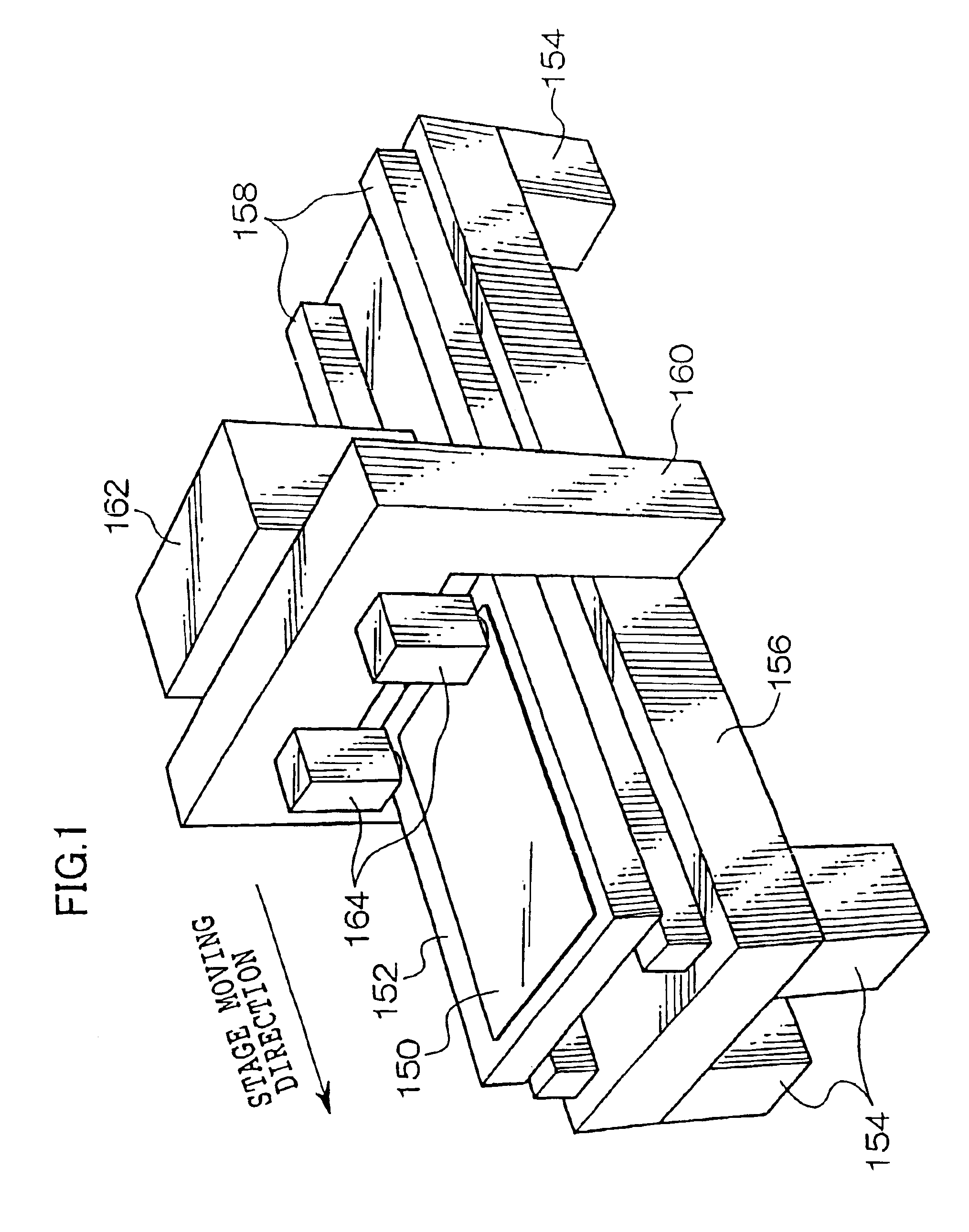
[0143]As shown in FIG. 1, the exposure apparatus according to the embodiment of the invention includes a flat plate-shaped stage 152 which absorbs a sheet-shaped photosensitive material 150 to a surface of the stage 152 and maintains the photosensitive material 150. Two guides 158 extending along a stage-moving direction are placed on an upper surface of a thick plate-shaped setting table 156 which is supported by four legs 154. While the stage 152 is arranged so that a longitudinal direction of the stage 152 faces the stage-moving direction, the stage 152 is supported by the guides 158 so as to be able to reciprocate. The exposure apparatus is provided with a driving device, which is not shown, for driving the stage 152 along the guides 158....

Example

[Second Embodiment]

[0260]A second embodiment of the invention is the embodiment of the rapid prototyping apparatus in which a photo-curable resin is exposed by the laser beam modulated with the spatial light modulator according to the image data to shape a three-dimensional model.

(Rapid Prototyping Apparatus)

[0261]As shown in FIG. 32, the rapid prototyping apparatus according to the embodiment of the invention includes a vessel 156 whose upper surface is opened, a liquid photo-curable resin 150 is stored in the vessel 156. A plate-shaped elevating stage 152 is arranged in the vessel 156, the elevating stage 152 is supported with a supporting portion 154 arranged outside the vessel 156. The supporting portion 154 is provided with an external thread portion 154A, and a lead screw 155 which is rotatable with a driving motor (not shown) is bolted in the external thread portion 154A. The elevating stage 152 is elevated by rotating the lead screw 155.

[0262]Above a liquid surface of the ph...

Example

[Third Embodiment]

[0284]A third embodiment is the embodiment of the stacking rapid prototyping apparatus in which powder is sintered to form a sintered layer by using the light beam modulated with the spatial light modulator according to the image data and the sintered layer is stacked to shape the three-dimensional model including powder-sintered material.

(Stacking Rapid Prototyping Apparatus)

[0285]As shown in FIG. 35, the stacking rapid prototyping apparatus according to the embodiment of the invention includes the vessel 156 whose upper surface is opened. The inside of the vessel 156 is divided into three portions in the lengthwise direction with two partitions, a shaping portion 153 for producing the shaped article is arranged in the central portion, and supplying portions 155 which supply powder 150 used for the shaping to the shaping portion 153 are arranged on both sides of the shaping portion 153.

[0286]The powder such as engineering plastic, metal, ceramics, sand, and wax ca...


PUM

PropertyMeasurementUnit
Wavelengthaaaaaaaaaa
Angleaaaaaaaaaa
Diameteraaaaaaaaaa

Abstract

In an exposure apparatus of the invention, for a spatial light modulator, each of a plurality of pixel portions fewer than the total number of the pixel portions is controlled with a control signal generated according to exposure information. Namely, a part of the pixel portions is controlled without controlling a whole of the pixel portions on the substrate. Thus, the number of pixels in the pixel portions is decreased, and transfer time of the control signal becomes short. This enables modulation speed of the laser beam to be increased and the high-speed exposure to be performed. An incorporated laser light source, in which the laser beams are incorporated and struck on the optical fiber, is preferable to the laser device. By adopting the incorporated laser light source, high brightness and high output can be obtained, and it is preferable to the exposure of the spatial light modulator. Since the fiber array is obtained with few optical fibers, it is low cost. Since the number of optical fibers is few, the light-emitting region is further decreased when the optical fibers are arrayed.

Description

BACKGROUND OF THE INVENTION[0001]1. Field of the Invention[0002]The present invention relates to an exposure head, an exposure apparatus, and application thereof, particularly relates to the exposure head which exposes a photosensitive material with a light beam modulated by a spatial light modulator according to image information, the exposure apparatus which includes the exposure head, and a rapid prototyping apparatus, a stacking rapid prototyping apparatus, and a bleaching apparatus to which the exposure apparatus is applied, and a forming method of a micro channel which utilizes the exposure apparatus.[0003]2. Description of the Related Art[0004]Conventionally, there has been proposed various kinds of the exposure apparatus which performs an image exposure with the light beam modulated according to the image data, utilizing the spatial light modulator such as a digital micro-mirror device (DMD).[0005]For example, DMD is a mirror device in which many micro-mirrors whose reflecti...

Claims


Application Information

Patent Timeline
IPC IPC(8): B41J2/435B41J2/465B41J2/447B41J2/47B29C67/00G02B26/08G03F7/20H04N1/191H04N1/12B23K26/06D06L4/50D06M10/00
CPCB23K26/0604B41J2/451B29C67/0066B29C67/0077B41J2/45B41J2/465B41J2/47D06L3/04D06M10/005G02B26/0841G03F7/2057G03F7/7005G03F7/70291H04N1/191H04N1/1916B23K26/0656H04N1/12B23K26/066D06L4/50B29C64/135B29C64/153B33Y30/00G03F7/20
Inventor ISHIKAWA, HIROMINAGANO, KAZUHIKOOKAZAKI, YOJIFUJII, TAKESHIYAMAKAWA, HIROMITSU
Owner FUJIFILM HLDG CORP
Why Eureka
Try Eureka