

Imaging lens
- Summary
- Abstract
- Description
- Claims
- Application Information
AI Technical Summary
Benefits of technology
Problems solved by technology
Method used
Image

Examples
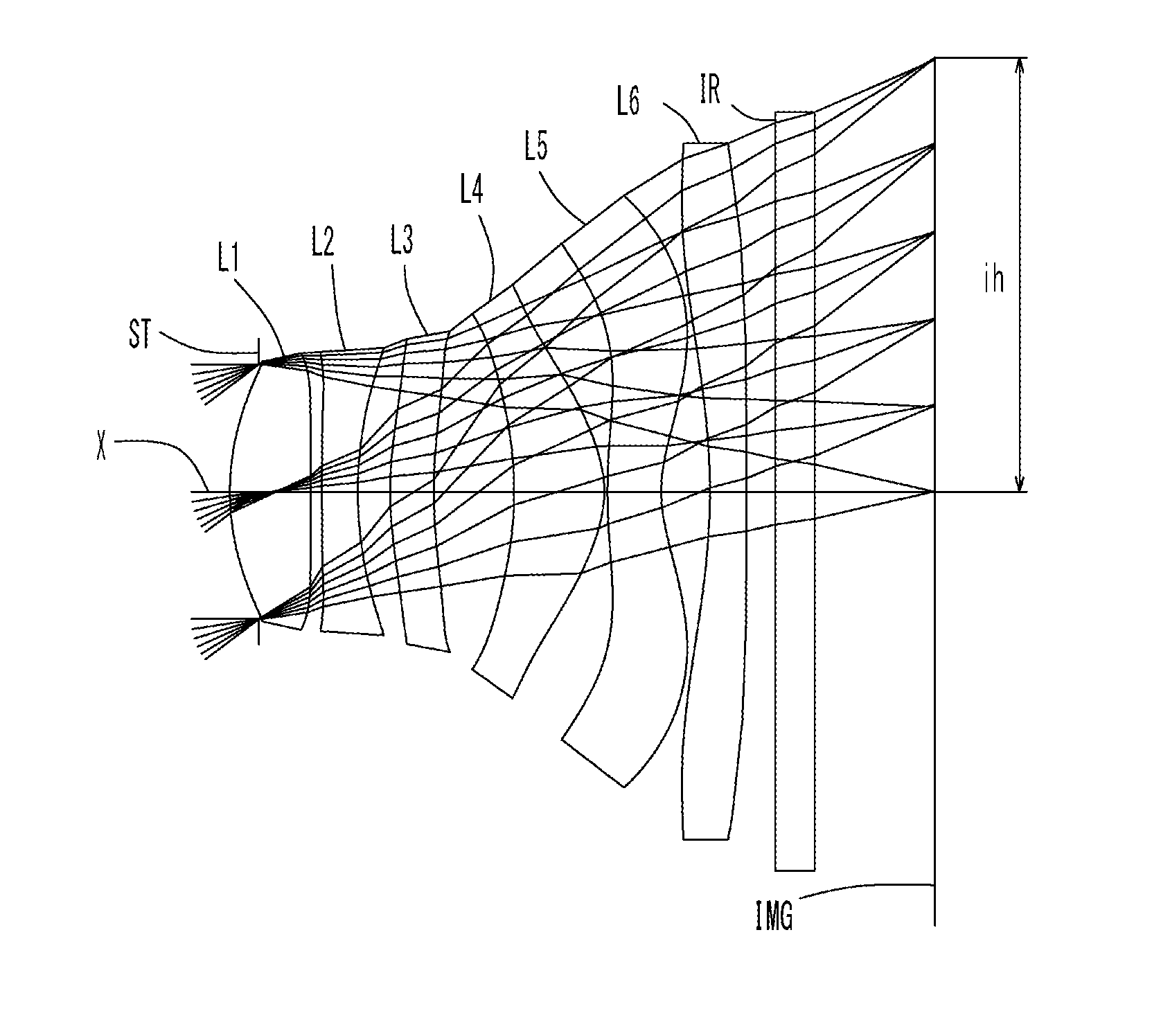
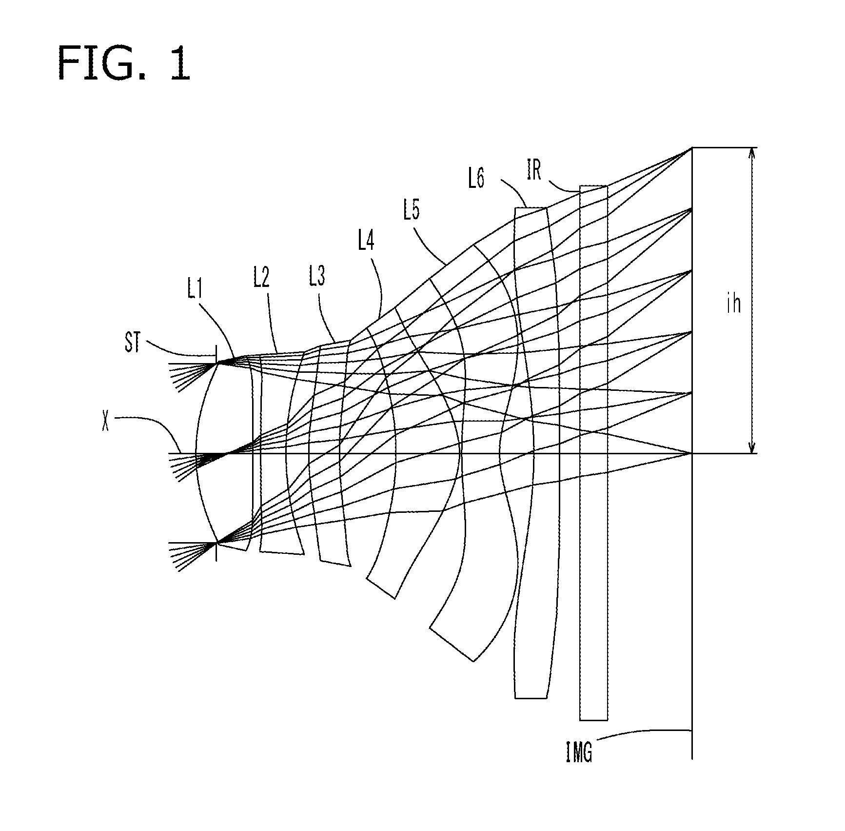
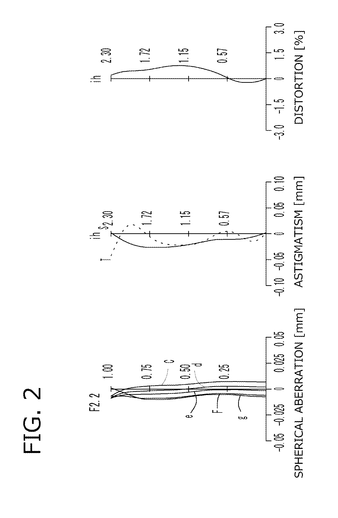
example 1
[0130]The basic lens data of Example 1 is shown in Table 1 below.
TABLE 1Example 1in mmf = 3.03Fno = 2.2ω(°) = 37.0ih = 2.30TLA = 3.65b f = 0.92Surface DataCurvatureSurfaceRefractiveAbbeSurface No. iRadius rDistance dIndex NdNumber vd(Object Surface)InfinityInfinity 1 (Stop)Infinity−0.155 2*1.34210.4281.54455.57 3*27.17440.058 4*7.87000.1901.63523.91 5*1.81650.171 6*1.80160.2311.53556.16 7*2.60070.425 8*−1.92490.4771.54455.57 9*−0.61430.01710*2.79740.2851.53556.1611*0.71220.25812*−3.46430.1951.53556.1613*−89.99820.15014Infinity0.2101.51764.2015Infinity0.631Image PlaneInfinityConstituent Lens DataLensStart SurfaceFocal Length122.58124−3.765369.964481.471510−1.877612−6.745Aspheric Surface Data2nd Surface3rd Surface4th Surface5th Surface6th Surface7th Surfacek4.059E−010.000E+000.000E+00−1.901E+010.000E+000.000E+00A4−5.184E−02 −3.080E−01 −5.306E−01 −1.049E−01−4.490E−01 −1.814E−01 A66.259E−021.952E+003.570E+00 1.608E+004.557E−011.438E−02A8−5.653E−01 −7.994E+00 −1.227E+01 −4.242E+00−5.831E...
example 2
[0134]The basic lens data of Example 2 is shown in Table 3 below.
TABLE 3Example 2in mmf = 3.04Fno = 2.2ω(°) = 37.0ih = 2.30TLA = 3.66bf = 0.83Surface DataCurvatureSurfaceRefractiveAbbeSurface No. iRadius rDistance dIndex NdNumber vd(Object Surface)InfinityInfinity 1 (Stop)Infinity−0.155 2*1.37120.4231.54455.57 3*49.19970.060 4*11.07520.1901.63523.91 5*1.87710.173 6*1.84650.2591.53556.16 7*3.04540.467 8*−2.05610.4561.54455.57 9*−0.65080.01510*2.59480.2941.53556.1611*0.73850.30012*−2.89050.1951.53556.1613*−90.00000.10014Infinity0.2101.51764.2015Infinity0.591Image PlaneInfinityConstituent Lens DataLensStart SurfaceFocal Length122.58624−3.588368.159481.571510−2.044612−5.590Aspheric Surface Data2nd Surface3rd Surface4th Surface5th Surface6th Surface7th Surfacek5.571E−010.000E+000.000E+00−2.084E+010.000E+000.000E+00A4−4.837E−02 −2.804E−01 −5.243E−01 −1.318E−01−4.676E−01 −1.808E−01 A64.875E−021.987E+003.689E+00 1.604E+004.493E−01−8.288E−03 A8−6.311E−01 −7.920E+00 −1.225E+01 −4.081E+00−6.09...
example 3
[0138]The basic lens data of Example 3 is shown in Table 5 below.
TABLE 5Example 3in mmf = 3.04Fno = 2.2ω(°) = 37.0ih = 2.30TLA = 3.66bf = 0.83Surface DataCurvatureSurfaceRefractiveAbbeSurface No. iRadius rDistance dIndex NdNumber vd(Object Surface)InfinityInfinity 1 (Stop)Infinity−0.155 2*1.37130.4311.54455.57 3*−90.00000.058 4*14.50690.1901.63523.91 5*1.91200.177 6*1.95270.2581.53556.16 7*3.15120.443 8*−2.05310.4701.54455.57 9*−0.65430.01710*2.54560.2901.53556.1611*0.74990.30212*−2.71050.1951.53556.1613*−88.94840.10014Infinity0.2101.51764.2015Infinity0.592Image PlaneInfinityConstituent Lens DataLensStart SurfaceFocal Length122.48824−3.489368.934481.579510−2.107612−5.233Aspheric Surface Data2nd Surface3rd Surface4th Surface5th Surface6th Surface7th Surfacek5.659E−010.000E+000.000E+00−2.162E+010.000E+000.000E+00A4−4.803E−02 −2.772E−01 −5.245E−01 −1.352E−01−4.715E−01 −1.807E−01 A64.930E−021.992E+003.697E+00 1.603E+004.522E−01−5.912E−03 A8−6.383E−01 −7.914E+00 −1.223E+01 −4.061E+00−6.0...
PUM
 Abstract
Description
Claims
Application Information