Capacitive type control member

a type control and capacitive technology, applied in the field of capacitive type control members, can solve the problems of large volume, lack of reliability, and long assembly time, and achieve the effect of improving the sensitivity of the touch detection space and increasing the user's perception

Inactive Publication Date: 2003-10-16
FAURECIA IND
View PDF5 Cites 14 Cited by
  • Summary
  • Abstract
  • Description
  • Claims
  • Application Information

AI Technical Summary

Benefits of technology

0018] One of the objects of the present invention is to provide novel improvements to the above-described capacitive type co

Problems solved by technology

However, it will be understood that such members present certain drawbacks, in particular concerning their bulkiness and their lack of reliability, particularly since they make use of moving parts.
Another problem associated with using members of that type lies in the complexity of assembling them and installing them on board the vehicle which requires the use of assembly components (screws, a pad support plate, etc. . . . ) and assembly time that is relatively lengthy.
Such detectors present the advantage of not requiring moving parts, but they suffer from a drawback of lack of feedback to the u

Method used


Image

  • Capacitive type control member
  • Capacitive type control member
  • Capacitive type control member

Examples


Embodiment Construction

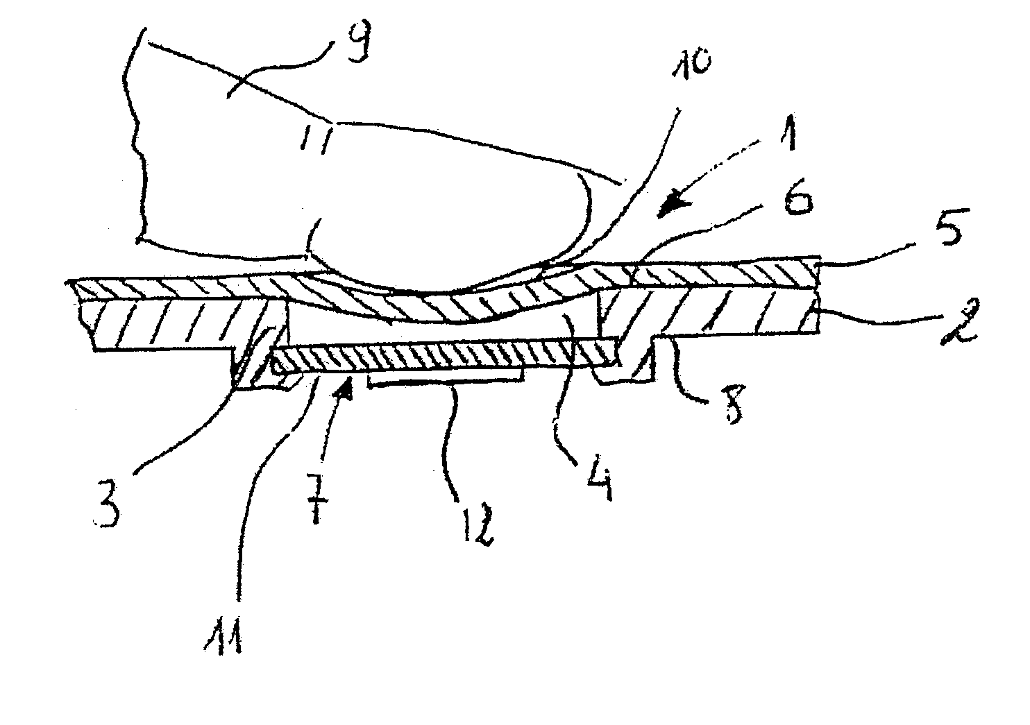
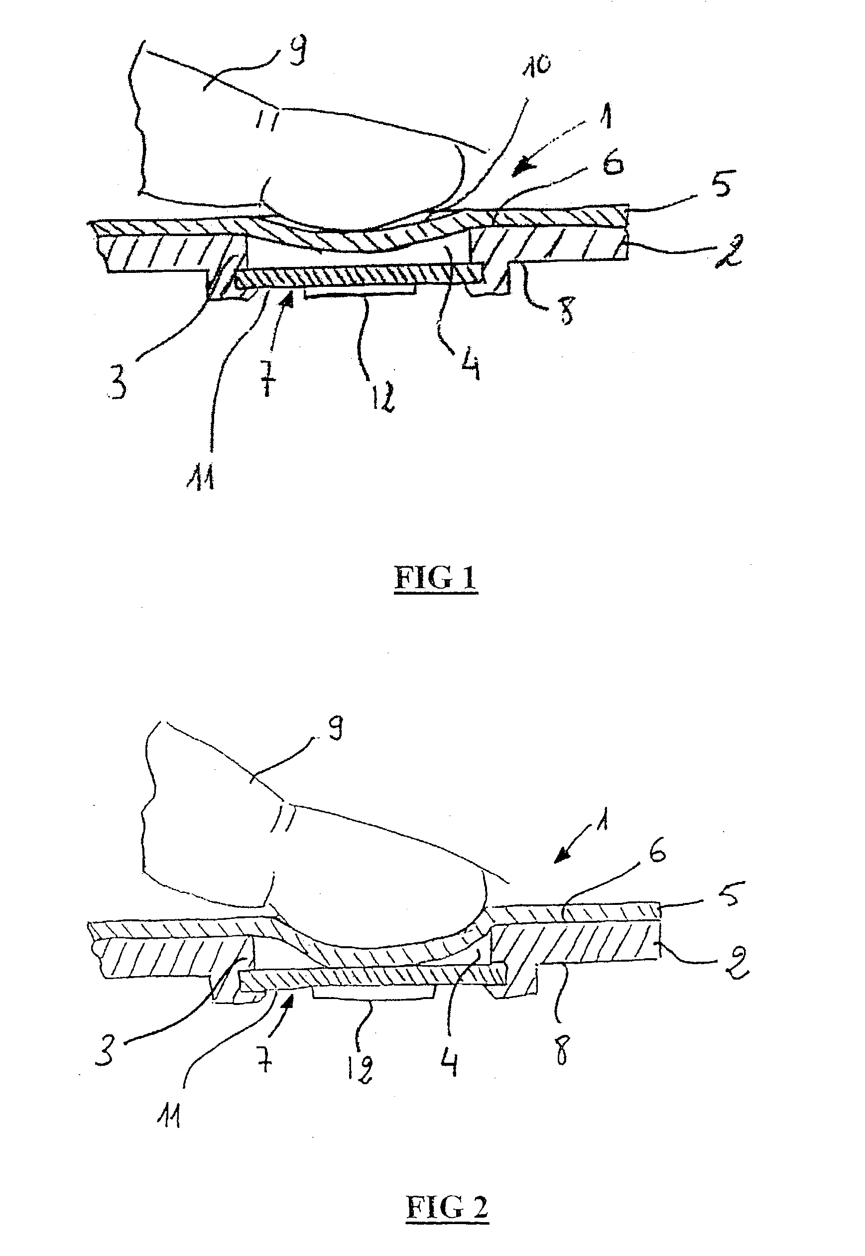
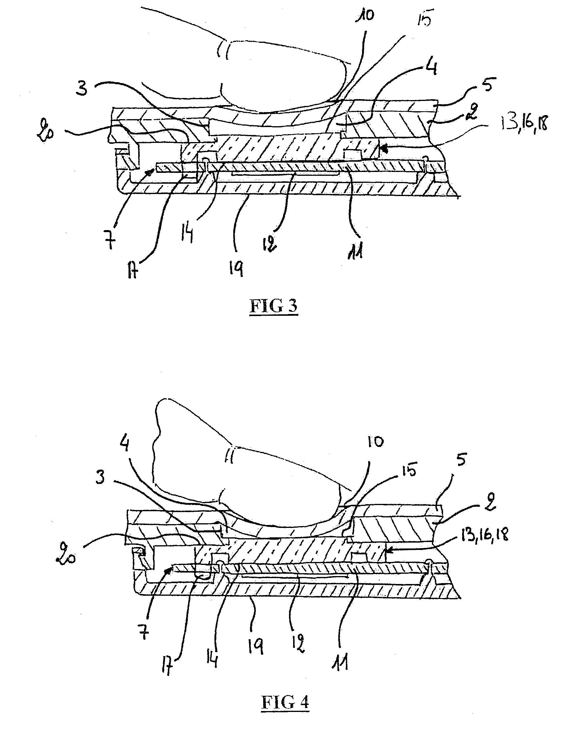
[0044] The present invention relates to a control member 1 of the capacitive type, comprising:

[0045] a support structure 2 presenting a control zone 3, said control zone 3 having a through hole 4;

[0046] a non-conductive elastic covering 5 covering a control face 6 of the control zone 3, at least in register with the through hole 4; and

[0047] a touch-sensitive detector 7 at least partially in register with the through hole 4 and mounted on or close to the face 8 of the control zone 3 that is opposite from its control face 6.

[0048] The elastic covering 5 has a rest position shown in FIGS. 1, 3, and 5 in which the finger 9 of an operator in contact with the free surface 10 of the resilient covering 5 lies outside the touch detection space of the detector 7, and a deformed position in which the finger 9 of the operator in contact with the free surface 10 of the elastic covering 5 lies within the touch detection space of the detector 7.

[0049] The term "touch detection space" is used to d...


PUM


Abstract

The member comprises: a support structure presenting a control zone, said control zone having a through hole; a non-conductive elastic covering covering a control face of the control zone, at least in register with the through hole; and a touch-sensitive detector at least partially in register with the through hole and mounted on or in the vicinity of the face of the control zone that is opposite from its control face; the elastic covering having a rest position in which the finger of an operator contacting the free surface of the elastic covering lies outside the touch detection space of the detector, and a deformed position in which the finger of the operator in contact with the free surface of the elastic covering lies within the touch detection space of the detector. According to the invention, in the rest position, the elastic covering is spaced apart from the touch-sensitive detector, and in the deformed position, the elastic covering is in contact with the touch-sensitive detector.

Description

[0001] The present invention relates to a control member of the capacitive type for controlling at least one functional member, in particular in a motor vehicle, and it also relates to a piece of vehicle equipment including such a member.[0002] Motor vehicle equipment is incorporating an increasing number of control members for controlling functional members of such vehicles.[0003] Several pieces of equipment placed in a vehicle cabin receive control members of this type which are thus made available to users of the vehicle.[0004] By way of example, these pieces of equipment can be constituted by door panels, the dashboard, or indeed a central console of the vehicle, etc.[0005] In general, the control members are grouped together to make up control pads made up of various kinds of member, such as, for example: switches, pushbuttons, or knobs for turning, which members are integrated in the electrical control circuits for the functional members.[0006] However, it will be understood t...

Claims


Application Information

Patent Timeline
IPC IPC(8): H01H9/18H01H13/52H01H13/00H01H13/02H03K17/96
CPCH03K17/962
Inventor BALP, LIONELBOCQUET, DENISHENIGUE, CHRISTIANROUDOT, JEAN-LUC
Owner FAURECIA IND
Why Eureka
Try Eureka