Air bag-use gas generator and air bag device

a gas generator and airbag technology, applied in the direction of pedestrian/occupant safety arrangement, vehicle components, vehicular safety arrangements, etc., can solve the problems of increasing a cost, complex structure, unsatisfactory, etc., and achieves satisfactory operation performance, simple structure, and reliably protecting the vehicle occupant

Inactive Publication Date: 2004-03-18
DAICEL CHEM IND LTD
View PDF7 Cites 4 Cited by
  • Summary
  • Abstract
  • Description
  • Claims
  • Application Information

AI Technical Summary

Benefits of technology

0022] The above gas generator for an air bag is accommodated in the module case together with an air bag (bag body) to introduce a gas generated in the gas generator to inflate, thereby being an air bag apparatus. In this air bag apparatus, the gas generator is activated upon the impact sensor detecting the impact to discharge an operation gas from the gas discharging port of the housing. The operation gas flows into the air bag, and thereby the air bag inflates to break a module cover and forms a cushion absorbing the impact between a hard structure in the vehicle and an occupant.
0023] The gas generator of the present invention provides a gas generator for an air bag which is simple in structure and that is activated to apply as small an impact as possible to a vehicle occupant at the initial stage of activation and can reliably protect the vehicle occupant by inflating the air bag rapidly at a subsequent activation stage.
0024] Next, the present invention provides a gas generator for an air bag having a structure capable of using even a gas generating agent whose ignitability is less than a gas generating agent conventionally used in gas generators. That is, it provides a gas generator which can exhibit satisfactory operation performance at the initial stage of operation even when it uses such a gas generating agent. Also, an air bag apparatus using this gas generator is provided.
0025] The above objective of this invention is achieved by an gas generator for an air bag comprising, in a housing having a gas discharging port, a substantially cylindrical inner cylindrical member disposed in the housing, an ignition means accommodating chamber for accommodating an ignition means defined inside the inner cylindrical member, a combustion chamber for accommodating a gas generating agent defined outside the inner cylindrical member, and plural f...

Problems solved by technology

However, in this art, there is a defect that the interior structure of the gas generator is complicated and the size of the container is made large, which results in factors of increasing a cost.
However, the structure is complicated and it is not satisfactory yet.
However, the gas generators provided so far could not gi...

Method used


Image

  • Air bag-use gas generator and air bag device
  • Air bag-use gas generator and air bag device
  • Air bag-use gas generator and air bag device

Examples


example 2

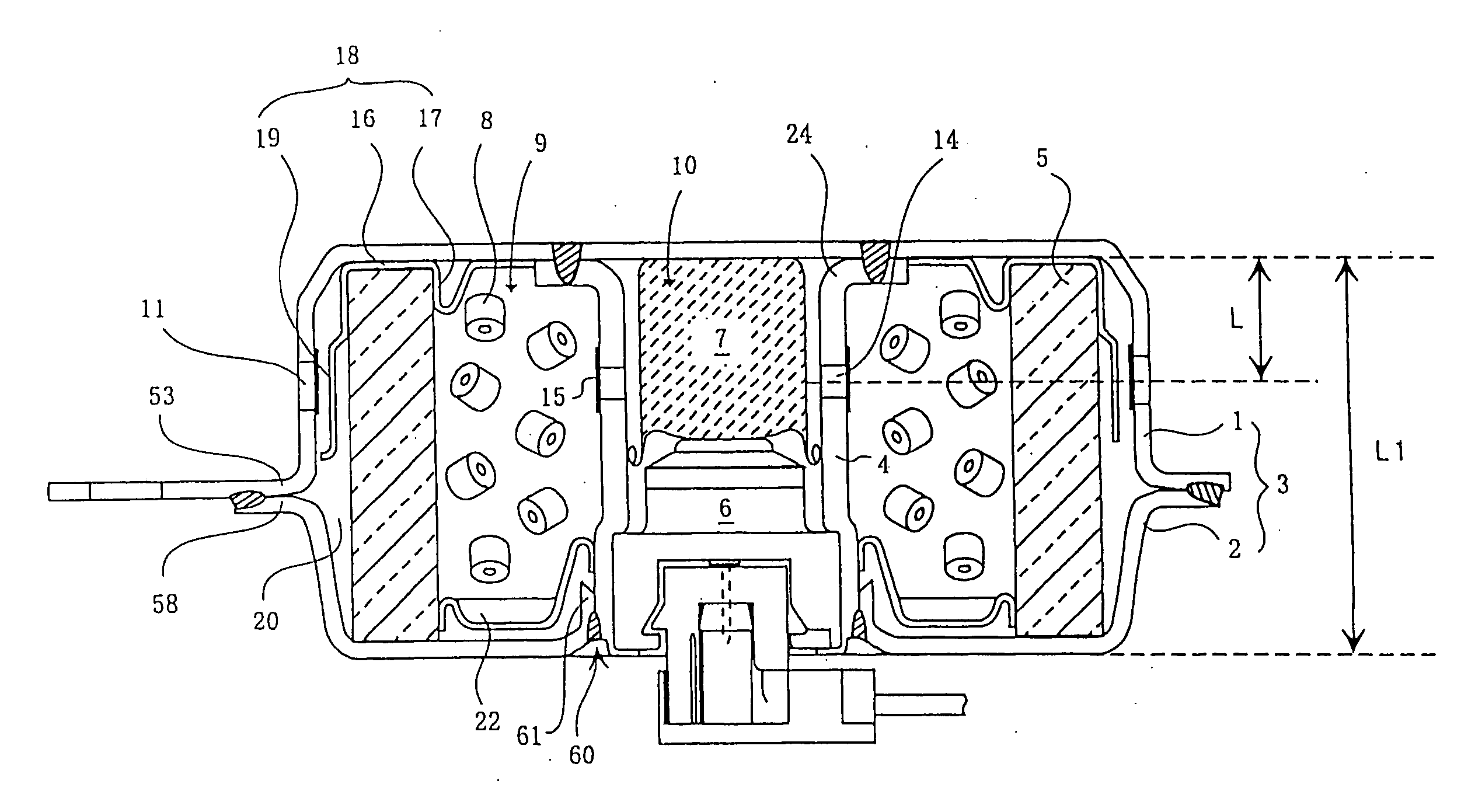
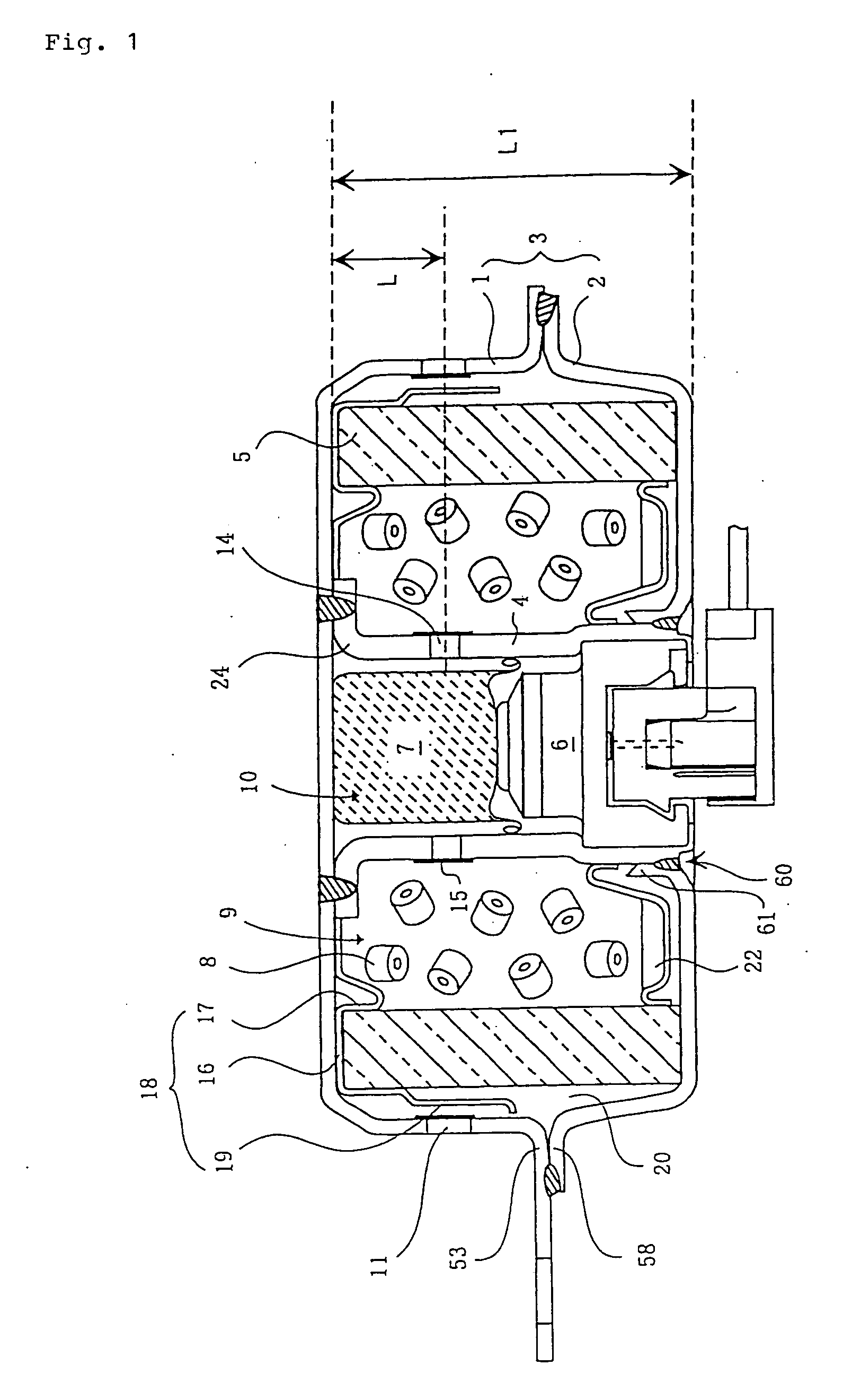
[0087] A tank combustion test was conducted using a gas generator shown in FIG. 1, and the time when the internal pressure of the housing reached the maximum (hereafter, also referred to as the time for the peak of the maximum internal pressure of the housing), after ignition electric current had been applied, was measured.

[0088] And, in the inner cylindrical member defining the ignition means accommodating chamber and the combustion chamber, flame-transferring holes described in the following (1) or (2) were formed as communicating portions which can make both chambers communicated with each other. The results are shown in FIG. 1.

[0089] And, the explanation of detail of the gas generator used in this example is omitted, with referring to the embodiment above.

[0090] (1) A gas generator in which 8 (eight) communicating portions comprising flame-transferring holes (enhancer nozzles) having the inner diameter of 2.2 mm were formed circumferentially in the inner cylindrical member, with...

embodiment 3

[0096] Embodiment 3 of the Invention

[0097] In FIG. 1, the gas discharging port 11 and the flame-transferring hole 14 are each sealed with a seal tape 15, and the gas generating agent 8 is supported by the underplate 22 and is accommodated in the combustion chamber. Also, the member described as the deflecting member 18 in this embodiment can function as a mist catching member or a flame preventing plate with the similar structure.

embodiment 4

[0098] Embodiment 4 of the Invention

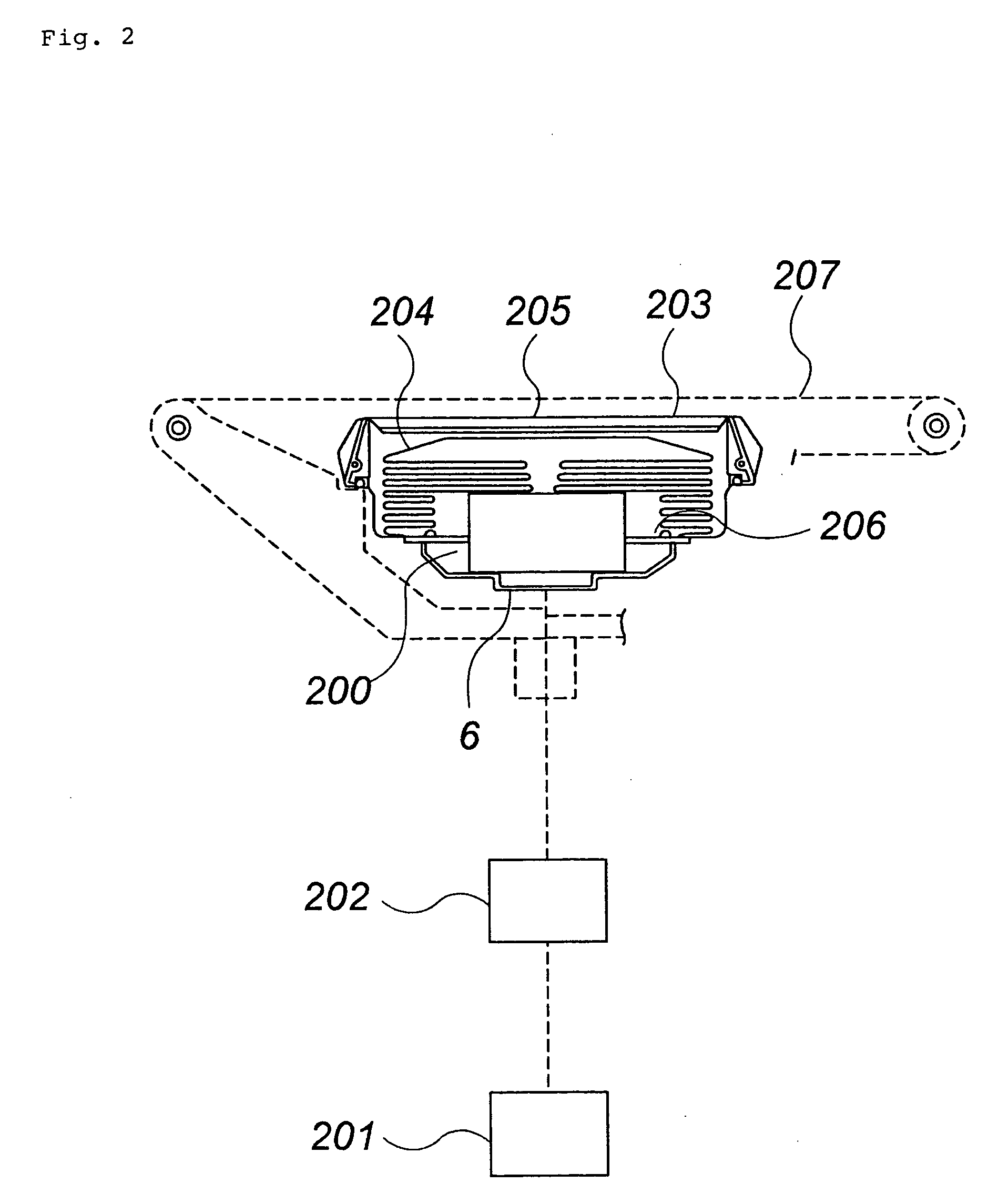
[0099] An example of an air bag apparatus of the present invention comprising a gas generator using an electric ignition type igniter is shown in FIG. 2.

[0100] This air bag apparatus comprises a gas generator 200, an impact sensor 201, a control unit 202, a module case 203 and an air bag 204. As gas generator 200, the gas generator explained based on FIG. 1 is used, and the operation performance thereof is adjusted such that it is activated to apply as small an impact as possible to a vehicle occupant at the initial stage of activation.

[0101] The impact sensor 201 may be, for example, a semiconductor type acceleration sensor. The semiconductor type acceleration sensor has four bridge-connected semiconductor strain gauges attached on a beam of silicon substrate that deflects when subjected to an acceleration.

[0102] When an acceleration is applied, the beam deflects causing strain on its surface, which in turn change the resistance of the semiconduc...


PUM


Abstract

A gas generator for an air bag having a simple structure, which is activated to apply as small an impact as possible to a vehicle occupant at the initial stage of activation and, thereafter, can reliably protect the vehicle occupant by rapidly increasing gas pressure, is provided. It is a gas generator for an air bag in which an inner cylindrical member is disposed in the housing to define an ignition means accommodating chamber and a combustion chamber, plural flame-transferring holes for communicating the both chambers with each other are formed on the circumferential surface of the inner cylindrical member, and the plural flame-transferring holes are formed at a distance of less than 30% of the axial length of the inner cylindrical member, from an end of the inner cylindrical member. A gas generator, which can use even a gas generating agent with less ignitability, and further can exhibit enough operation performance at the initial stage of activation even when using such a gas generating agent, is provided. It is a gas generator for an air bag in which an inner cylindrical member is disposed in the housing to define an ignition means accommodating chamber and a combustion chamber, and the central angle formed by the adjacent communicating portions which are formed on the circumferential surface of the inner cylindrical member is adjusted to be not more than 60 degrees.

Description

TECHNICAL FIELD TO WHICH THE INVENTION BELONGS[0001] The present invention relates to a gas generator for an air bag for protecting a vehicle occupant from the impact, particularly, to a gas generator for an air bag characterized in its operation performance, and an air bag apparatus.RELATED ART[0002] In a vehicle such as an automobile, in order to prevent the passenger from crashing into a hard portion inside the vehicle such as a steering wheel and a windshield due to an inertia and being injured or dying when the vehicle collides at a high speed, an air bag system, which inflates an air bag rapidly with a gas to protect the passenger from colliding with such a dangerous portion, is provided.[0003] It is desirable that such an air bag system can safely restrain the vehicle occupant even when the frame of the vehicle occupant (for example, whether a sitting height is high or low, whether an adult or a child, and the like), a sitting attitude (for example, an attitude of holding on ...

Claims


Application Information

Patent Timeline
IPC IPC(8): B60R21/26B60R21/264
CPCB60R21/2644B60R21/26
Inventor MIYAJI, KATSUHITOIWAI, YASUNORI
Owner DAICEL CHEM IND LTD
Why Eureka
Try Eureka