Local oscillator using I/Q mismatch compensating circuit through LO path receiver using thereof

a local oscillator and compensating circuit technology, applied in the field of conventional radio frequency receivers, can solve the problems of significant problem in the system of direct conversion receiver and image-removing receiver, the characteristic of delay cells of the local oscillator is not ideal, and the error rate increases, so as to achieve the effect of convenient application

Inactive Publication Date: 2004-05-13
INTEGRANT TECH
View PDF15 Cites 26 Cited by
  • Summary
  • Abstract
  • Description
  • Claims
  • Application Information

AI Technical Summary

Benefits of technology

[0011] Still other object of the present invention is to provide a circuit for correcting phase mismatch between in-phase signal and quadrature-phase signal without substantially affecting gain, noise and linearity and the like of overall system.
[0012] Still further object of the present invention is to provide a circuit for correcting in-phase signal and quadrature-phase signal that can be easily applied to already-manufactured circuit.

Problems solved by technology

If the difference between the phases of LO.sub.I and LO.sub.Q does not equal 90 degree, bit error rate increases in the restored signal. in particular, tile mismatch between in-phase signal I and quadrature-signal Q causes significant problem in the system of direct-conversion receiver and image-removing receiver.
However, the characteristic of delay cells of the local oscillator does not ideally match due to thickness of insulator, device size, space difference, various crystal structure of semiconductor material, mismatch of layout and the like.
This is an important cause of generating mismatch between I / Q signals of the receiver.
Further, mismatch between devices in way of I and Q path of the receiver is one of causes generating I / Q mismatch of radio frequency receiver.
However, phase mismatch may cause significant problem due to path difference between two signals and device characteristic as frequency increase.
The addition of correction circuit to a path where signal passes may degrade gain, noise, linearity and the like.
Further, it is difficult to apply the technique in already-manufactured circuit,

Method used


Image

  • Local oscillator using I/Q mismatch compensating circuit through LO path receiver using thereof
  • Local oscillator using I/Q mismatch compensating circuit through LO path receiver using thereof
  • Local oscillator using I/Q mismatch compensating circuit through LO path receiver using thereof

Examples


Embodiment Construction

[0030] In the following, the preferred embodiment of the present invention will be described in detail with reference to attached drawings.

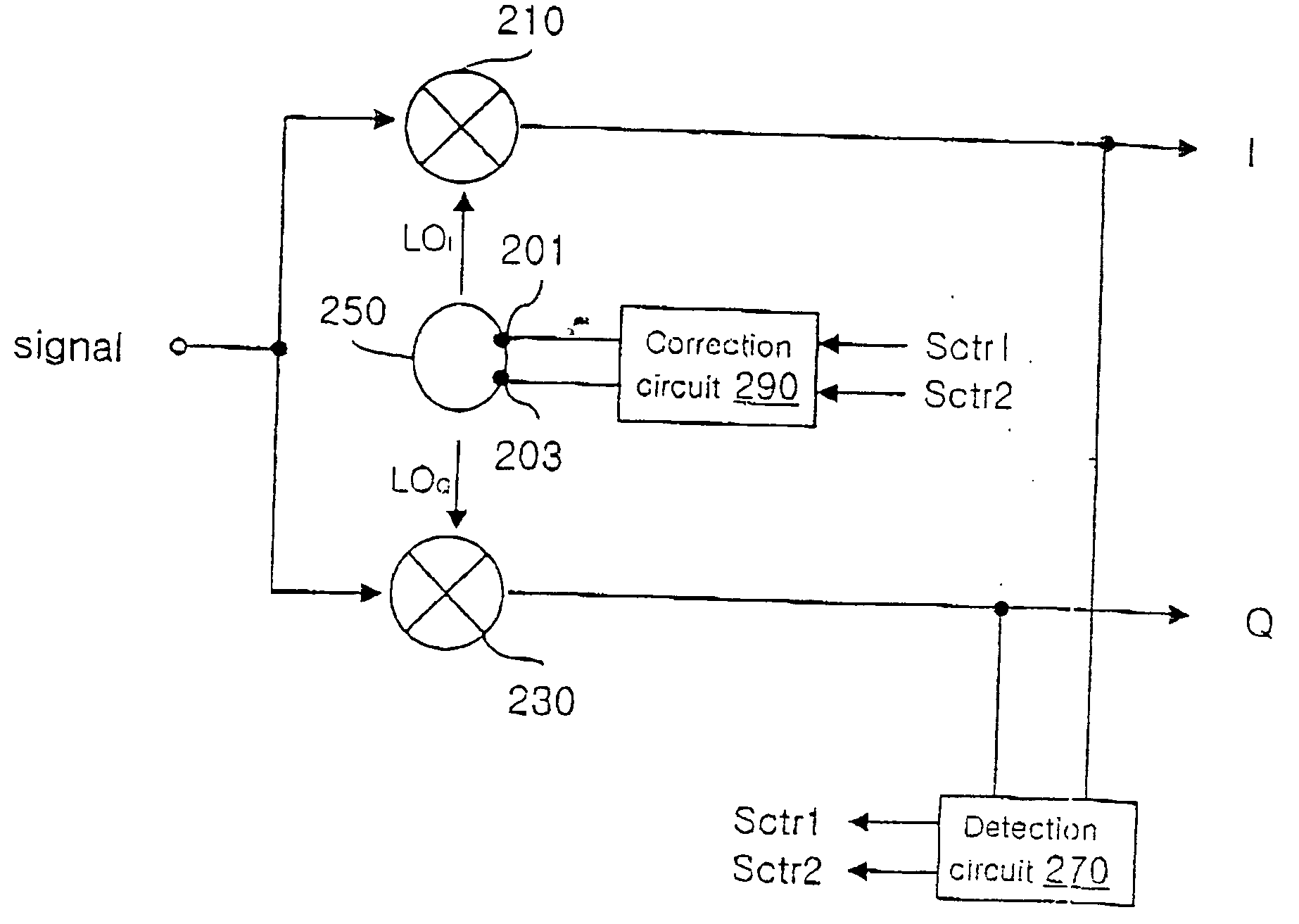
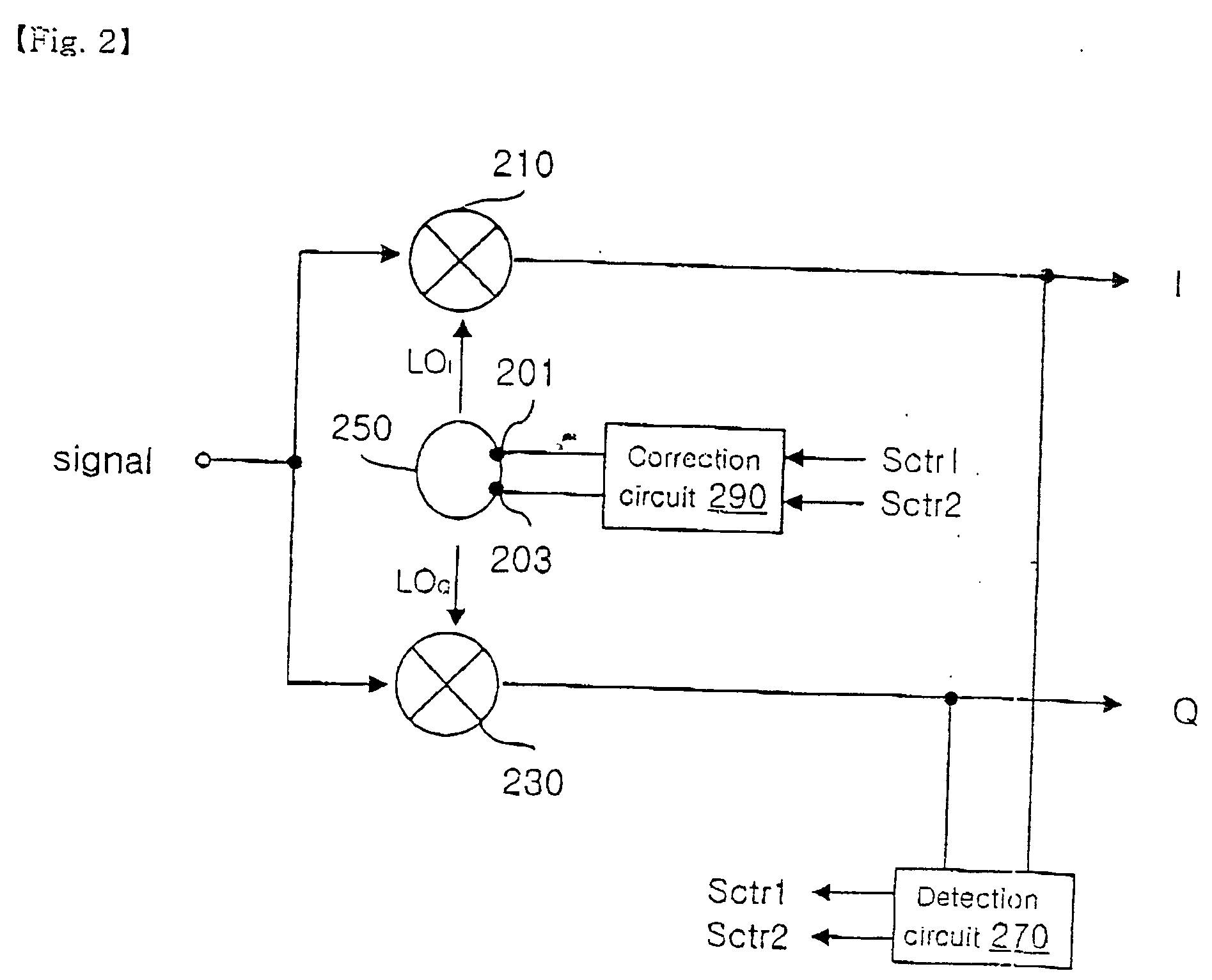
[0031] FIG. 2 shows a circuit diagram of an embodiment of the present invention.

[0032] As shown in FIG. 2. the receiver comprises first and second mixers 210, 230, local oscillator 250, detection circuit 270, correction circuit 290.

[0033] First and second mixers 210, 230 mix in-phase signal LO.sub.I and quadrature-phase signal LO.sub.Q with input signal, respectively, to output base band or intermediate frequency (IF) signal.

[0034] Local oscillator 250 has first and second correction nodes 201, 203 and outputs in-phase local oscillating signal LO.sub.I and quadrature-phase signal LO.sub.Q which have the same amplitude. The phases of the signals substantially differs each other by 90 degrees. Matching characteristic of in-phase local oscillating signal LOI and quadrature-phase signal LOQ are controlled by correction signal applied to first and sec...


PUM


Abstract

This invention relates to a local oscillator using a correction circuit for correcting I / Q mismatch through LO path and a receiver using the same. The local oscillator provides in-phase local oscillating signal and quadrature-phase signal to first and second mixers outputting input signal with mixing in-phase local oscillating signal and quadrature-phase local oscillating signal, respectively. The oscillator comprises a local oscillator having first and second delay cells and outputting said in-phase local oscillating signal and said quadrature-phase local oscillating signal; and a correction circuit for controlling phase matching characteristic between said in-phase local oscillating signal and said quadrature-phase local oscillating signal outputted from said local oscillator, said correction circuit setting bias current flowing in said first and second delay cells of said local oscillator as being different. In another embodiments, the phase matching characteristic is controlled by setting bias voltage applied to the first and second delay cells as being different, by setting width of active device included in the first and second delay dells as being different, or by setting impedance of passive device as being different.

Description

[0001] The present invention relates to a communication system. Specifically, the invention is directed to a circuit for compensating phase mismatch generated between in-phase signal and quadrature-phase signal of a receiver.BACKGROUND OF INVENTION[0002] FIG. 1 shows a schematic circuit diagram of the conventional radio frequency receiver.[0003] As shown in FIG. 1, the conventional radio frequency receiver comprises a low-noise amplifier 110, first and second mixers 120, 130, a local oscillator 140 and first and second base-band circuits 150, 160.[0004] Low-noise amplifier 110 amplifies radio frequency signal received by an antenna to apply the signal to first and second mixers 120, 130. First and second mixers 120, 130 mix the amplified radio frequency signal with in-phase local oscillating signal LO.sub.I and quadrature-phase local oscillating signal LO.sub.Q to output intermediate frequency or base band signal, respectively. First and second base-band circuits 150, 160 amplify / fi...

Claims


Application Information

Patent Timeline
Patent Type & Authority Applications(United States)
IPC IPC(8): H04B1/06H03D3/00H04B1/04H04B1/30H04L27/00
CPCH03D3/009H04B1/0475H04L2027/0024H04L2027/0016H04B1/30H04B1/06
Inventor KIM, BON-KEEKIM, BO-EUN
Owner INTEGRANT TECH
Why Eureka
Try Eureka