Ultra-fast precision motor with X, Y and Theta motion and ultra-fast optical decoding and absolute position detector

a precision motor and ultra-fast technology, applied in the direction of motor/generator/converter stopper, motor/generator control, instruments, etc., can solve the problem that the high-speed layer does not have flexible wires, and achieve the effect of facilitating higher overall performan

a precision motor and ultra-fast technology, applied in the direction of motor/generator/converter stopper, motor/generator control, instruments, etc., can solve the problem that the high-speed layer does not have flexible wires, and achieve the effect of facilitating higher overall performan

US20050001579A1Inactive Publication Date: 2005-01-06TOUZOV IGOR

Image

  • Ultra-fast precision motor with X, Y and Theta motion and ultra-fast optical decoding and absolute position detector
  • Ultra-fast precision motor with X, Y and Theta motion and ultra-fast optical decoding and absolute position detector
  • Ultra-fast precision motor with X, Y and Theta motion and ultra-fast optical decoding and absolute position detector

Examples


Embodiment Construction

[0050] The basic idea of the invention is a combination of extreme durability and ultra fast positioning. Yet another revolutionary result is lateral mobility over large macroscopic distances with sub-nanometer precision which is achievable over full motion range and completely unconstrained by either extreme speeds or accelerations of the movements. Invention consists of two major parts which are: positioning stage with Y, Y and rotational degrees of freedom; and absolute position detector that uses spatial encoding and provides guaranteed precision in lateral position detection.

POSITIONING STAGE

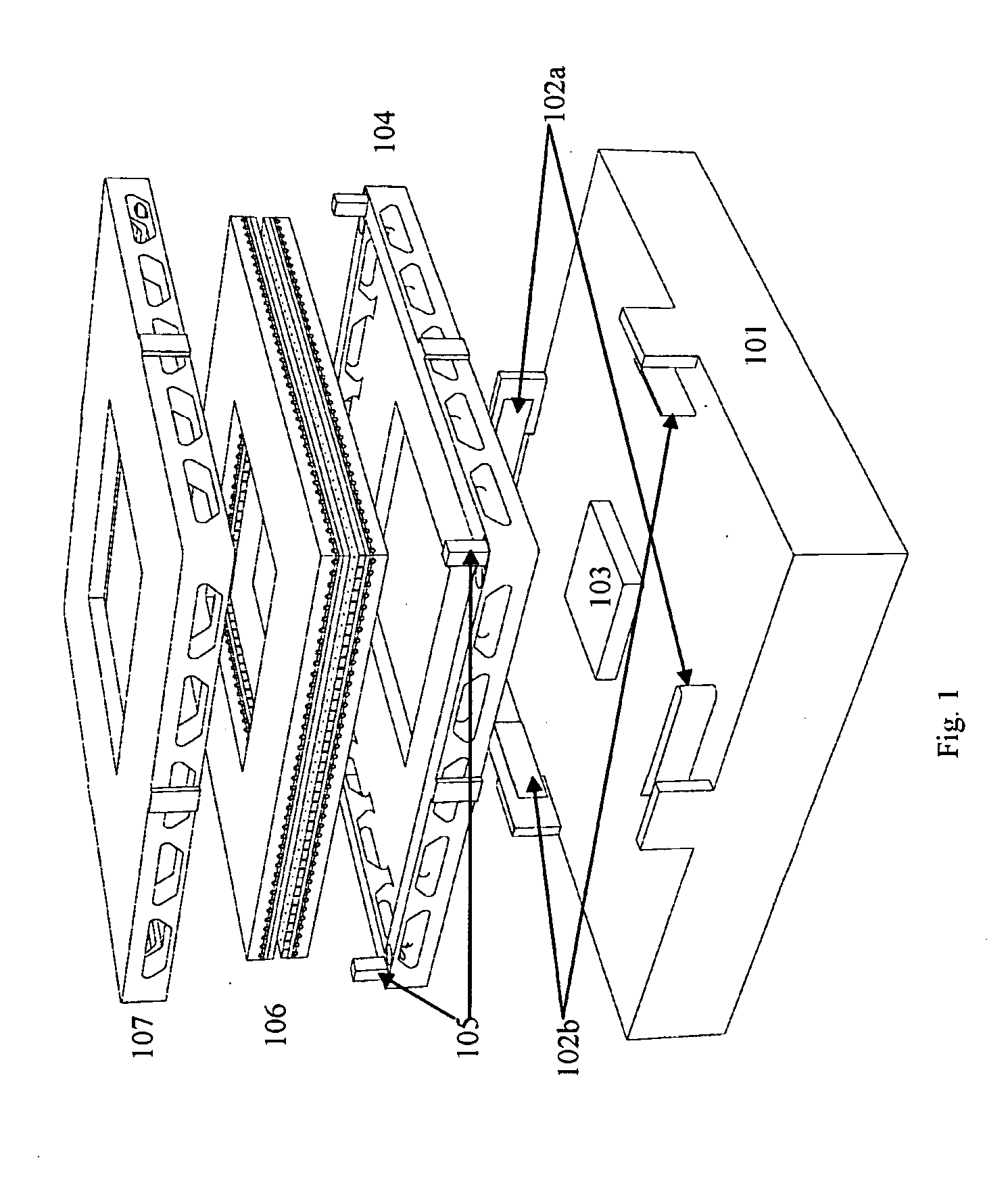
[0051] This embodiment focuses on detailed description of mechanical structure of the positioning stage. Overview of the apparatus is shown on FIG. 1. Components of the stage are supported by the base 101 which provides an interface with flexible wiring and tubing 102a-b for mobile base 104, 107. It also holds detector head 103 of the absolute position detector which in some cases may be ...


PUM


Abstract

Ultra-fast precision motor with X, Y and Theta motion and ultra-fast optical decoding and absolute position detector A high-speed and extremely large range positioning apparatus capable of producing motions in multiple dimensions with high precision and very high reliability. An ultra fast absolute position sensor providing instantaneous position readings with sub nanometer precision on full range of relative positions. A set of optical encoding schemas providing high encoding density and extremely fast decoding regardless of their planar positions. A flexible reshape-able motor with multiple degrees of motions

Description

CROSS REFERENCE TO RELATED APPLICATIONS [0001] This application is a regular application of provisional Patent Application No. 60 / 481,005, filed Jun. 21, 2003 which is hereby incorporated by reference in its entirety for all purposesBACKGROUND OF INVENTION [0002] This invention relates to high-speed positioning apparatuses useful for nano- and micro-scale technological applications, such as semiconductor wafer processing, chemical substance deposition, and experimentation with bio-organic materials, scanning microscopy, or other applications which include macro scale transport equipment and positioning devices. [0003] Nano-technological applications often require high precision positioning of substrate combined with large range of motion. Time between elementary processing steps always needs to be minimal to accommodate low contamination level, small feature sizes and process throughput. [0004] Typical example of nano-technological process is micro-contact deposition of chemicals us...

Claims


Application Information

Patent Timeline
06 Jan 2005
Publication
US20050001579A1
IPC
B64C17/06; H02K11/00; H02K41/03; H03F3/04; H03F3/68
CPC
H02K11/0026; H02K2201/18; H02K41/03; H02K11/22
Inventors
TOUZOV, IGOR V.