Cooling using complimentary tapered plenums

Active Publication Date: 2005-02-03
IBM CORP
View PDF15 Cites 27 Cited by
  • Summary
  • Abstract
  • Description
  • Claims
  • Application Information

AI Technical Summary

Benefits of technology

It is an object of the invention to provide an arrangement for the flow

Problems solved by technology

Thus space is wasted near the top of the cold plenum.
T

Method used


Image

  • Cooling using complimentary tapered plenums
  • Cooling using complimentary tapered plenums
  • Cooling using complimentary tapered plenums

Examples


Example

Variations described for the present invention can be realized in any combination desirable for each particular application. Thus particular limitations, and / or embodiment enhancements described herein, which may have particular advantages to the particular application need not be used for all applications. Also, it should be realized that not all limitations need be implemented in methods, systems and / or apparatus including one or more concepts of the present invention.

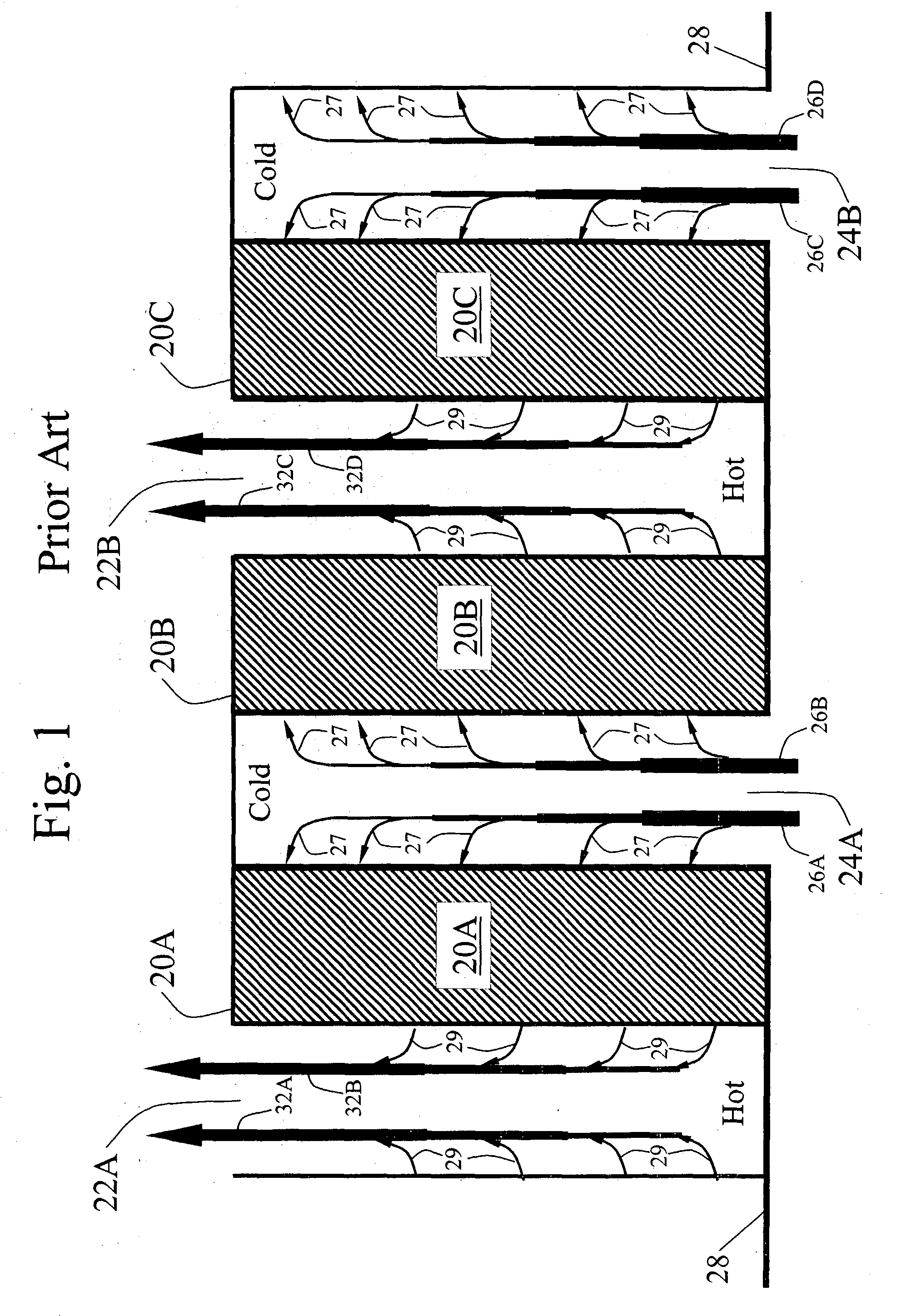
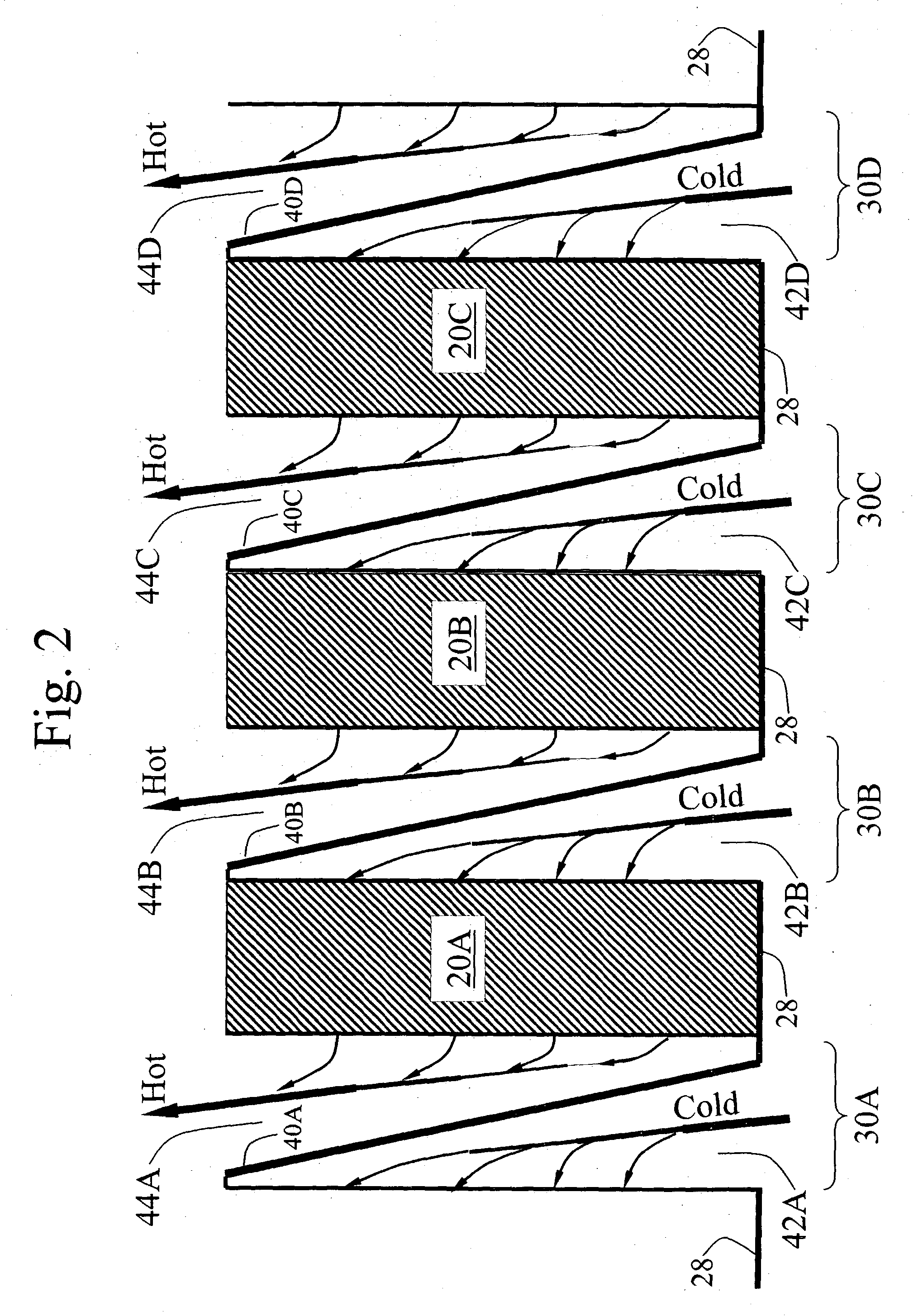
Referring to FIG. 2, the inter-rack spaces 30A, 30B, 30C, 30D (configured in the prior art of FIG. 1 as alternating hot and cold plenums 22A, 24A, 22B, and 24B) are instead r configured, in accordance with the invention, by dividing each inter-rack space, via a sloping partition, into a complimentary pair of tapered hot and cold plenums. Thus the inter-rack space 30A is divided by sloping partition 40A into the cold plenum 42A and hot plenum 44A; the inter-rack space 30B is divided by sloping partition 40B into co...


PUM


Abstract

Where a fluid cooling medium cools a plurality of heat-producing devices arranged in a row along a generalized coordinate direction, with a space between each adjacent pair of devices, each space may have a partition that defines a boundary between a first plenum and a second plenum. The first plenum carries cooling medium across an entrance and thence into a first heat-producing device located on a first side of the partition facing the first plenum. The second plenum carries cooling medium away from a second heat-producing device located on a second side of the partition facing the second plenum and thence across an exit. The partition is disposed so that the first plenum becomes smaller in cross-sectional area as distance increases from the entrance, and the second plenum becomes larger in cross sectional area as distance decreases toward the exit.

Description

FIELD OF THE INVENTION This invention relates to the cooling of equipment that produces heat, and in particular to the cooling of electronic equipment. More particularly it is related to apparatus and methods used to cool racks of electronic equipment, and still more particularly to racks of electronic equipment of the type used in a data storage center. BACKGROUND OF THE INVENTION For air-cooled, heat-producing electronic equipment requiring two or more racks arranged in rows on a raised floor, such as in a large computer installation, the cooling system may cause air to flow across the electronics in any of the three coordinate directions. Let X be the direction along a row, Y be perpendicular to the rows, and Z be upward. For systems in which the air flows across the electronics in the X direction, air-flow plenums typically must exist between each pair of racks. FIG. 1 illustrates a prior-art arrangement of such plenums, 22A, 24A, 22B, 24B, interspersed between a row of heat-p...

Claims


Application Information

Patent Timeline
IPC IPC(8): H05K7/20
CPCH05K7/20572
Inventor HALL, SHAWN ANTHONY
Owner IBM CORP
Why Eureka
Try Eureka