Vehicle drive apparatus

a technology of drive apparatus and drive shaft, which is applied in the direction of electric propulsion mounting, electric devices, transportation and packaging, etc., can solve the problems of large motor size, and achieve the effect of large output capacity, high torque and sufficient torqu

Inactive Publication Date: 2005-03-31
NISSAN MOTOR CO LTD
View PDF6 Cites 8 Cited by
  • Summary
  • Abstract
  • Description
  • Claims
  • Application Information

AI Technical Summary

Benefits of technology

[0006] It has been discovered that, when the motor-driven wheels that are not driven by the engine are driven with a single electric motor as disclosed in the conventional vehicle drive apparatus in the above mentioned reference, the electric motor is required to have a large output capacity in order to provide both high torque at low rotational speeds and sufficient torque at medium to high rotational speeds. One feasible method of increasing the output of the electric motor is to increase the number of coil windings and raise the magnetic flux of the motor. However, increasing the number of coil windings causes the size of the motor to become large.
[0007] In view of the above problem, one object of the present invention is to provide a vehicle drive apparatus that is capable of driving a wheel or wheels with a plurality of drive sources to prevent the size of a single drive source from becoming large and capable of sufficiently accommodating rotational speeds ranging from low speeds to high speeds.

Problems solved by technology

However, increasing the number of coil windings causes the size of the motor to become large.

Method used


Image

  • Vehicle drive apparatus
  • Vehicle drive apparatus
  • Vehicle drive apparatus

Examples


second embodiment

[0062] Referring now to FIGS. 5 and 6, a vehicle drive apparatus in accordance with a second embodiment will now be explained. In view of the similarity between the first and second embodiments, the parts of the second embodiment that are identical to the parts of the first embodiment will be given the same reference numerals as the parts of the first embodiment. Moreover, the descriptions of the parts of the second embodiment that are identical to the parts of the first embodiment may be omitted for the sake of brevity.

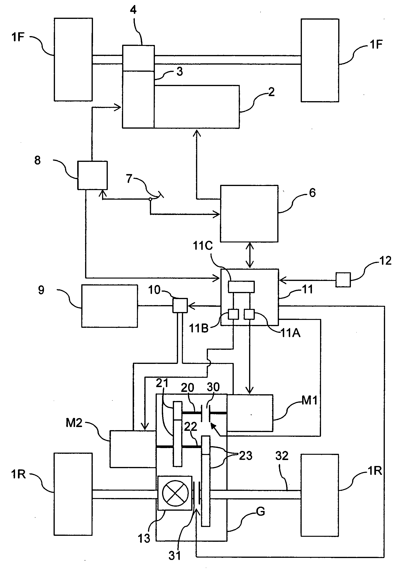
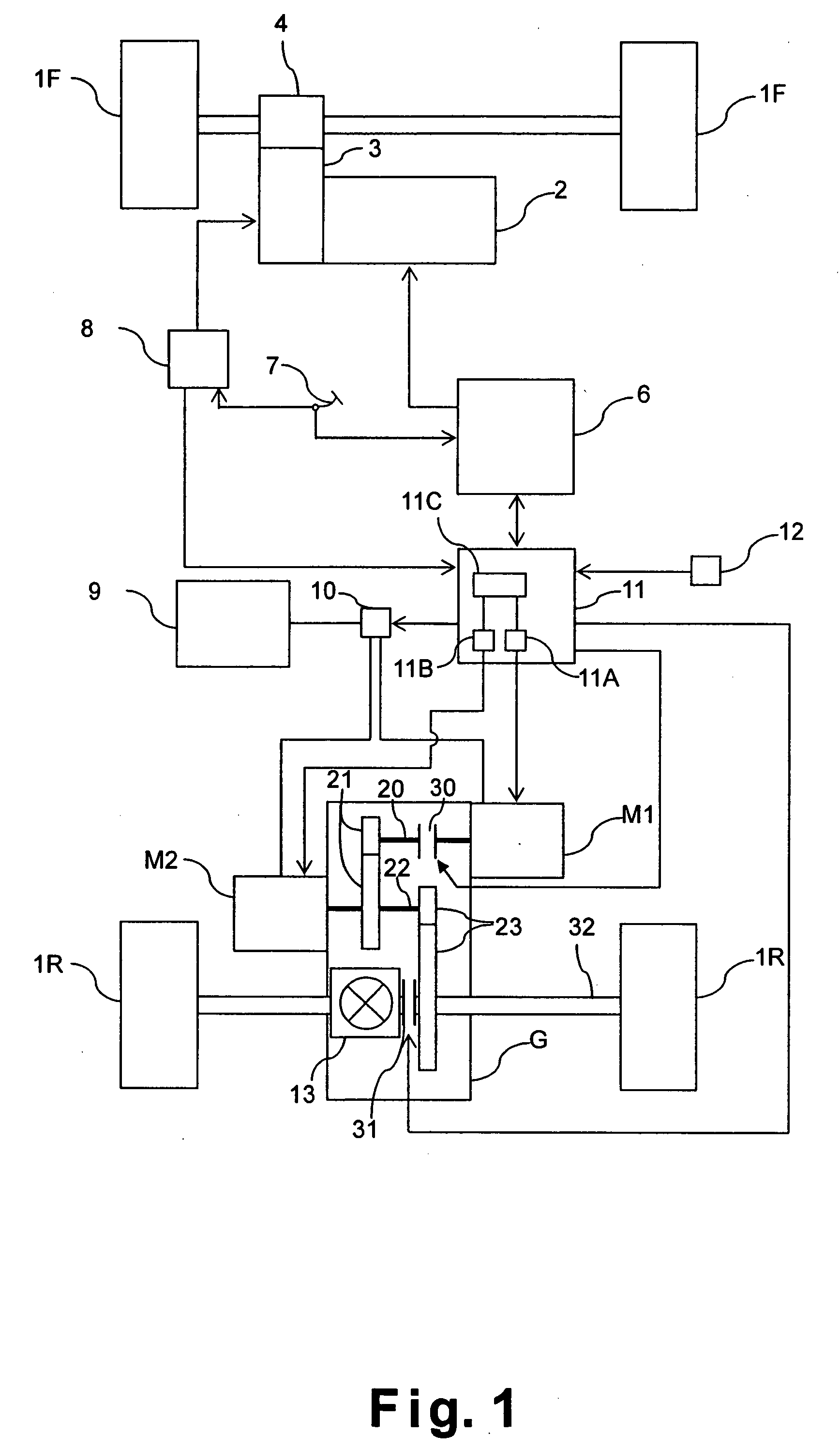
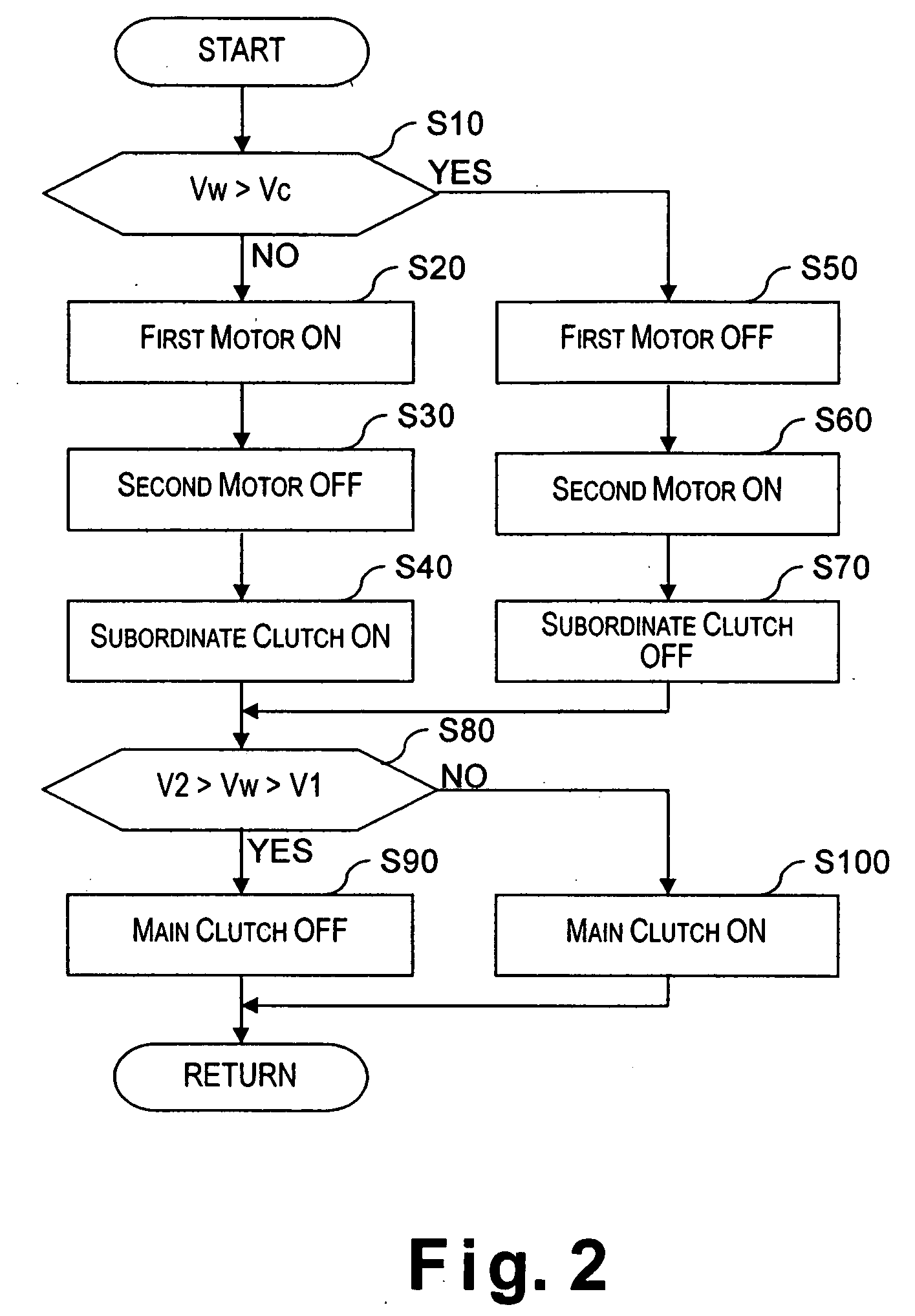
[0063] The basic constituent features of the vehicle drive apparatus of the second embodiment are identical to the vehicle drive apparatus of the first embodiment as shown in FIG. 1. The second embodiment of the present invention differs from the first embodiment in that the control executed in the motor control main unit 11C is slightly different from the control in the first embodiment. More specifically, in the second embodiment of the present invention, the rele...

third embodiment

[0077] Referring now to FIGS. 7 and 8, a vehicle drive apparatus in accordance with a third embodiment will now be explained. In view of the similarity between the previous embodiments and third embodiments, the parts of the third embodiment that are identical to the parts of the previous embodiments will be given the same reference numerals as the parts of the previous embodiments. Moreover, the descriptions of the parts of the third embodiment that are identical to the parts of the previous embodiments may be omitted for the sake of brevity.

[0078] The basic constituent features of the vehicle drive apparatus of the third embodiment are identical to the vehicle drive apparatus of the first embodiment as shown in FIG. 1. The third embodiment of the present invention differs from the previous embodiments in that the control executed in the motor control main unit 11C is slightly different from the control in the previous embodiments. More specifically, in the third embodiment of the...


PUM


Abstract

A vehicle drive apparatus is provided that comprises first and second drive sources, a main clutch, a subordinate clutch, a drive source selecting section, and a clutch control section. The first and second drive sources output drive forces to a first wheel. The main clutch is configured to simultaneously shut off delivery of outputs from the first and second drive sources. The subordinate clutch coupled to the first drive source is configured to shut off delivery of only the output from the first drive source. The drive source selecting section is configured to select at least one of the first and second drive sources to output the drive force. The clutch control section is configured to release the subordinate clutch while the main clutch is temporality released upon a determination of the first drive source being switched from an output delivery state to an output stop state.

Description

BACKGROUND OF THE INVENTION [0001] 1. Field of the Invention [0002] The present invention generally relates to a vehicle drive apparatus. More specifically, the present invention relates to a vehicle drive apparatus configured and arranged such that a wheel or wheels can be driven with a plurality of drive sources. [0003] 2. Background Information [0004] One example of a conventional vehicle drive apparatus configured such that the front and rear wheels can be driven with a plurality of drive sources is disclosed in Japanese Laid-Open Utility Model Publication No. 55-138129. This reference discloses a four-wheel drive vehicle in which one of a pair of front wheels or a pair of rear wheels is driven with an engine and the other pair of wheels that is not driven with the engine is driven with a motor. [0005] In view of the above, it will be apparent to those skilled in the art from this disclosure that there exists a need for an improved vehicle drive apparatus. This invention address...

Claims


Application Information

Patent Timeline
Patent Type & Authority Applications(United States)
IPC IPC(8): B60K1/02B60K17/00B60K6/26B60K6/387B60K6/40B60K6/44B60K6/52B60K6/54B60K7/00B60K17/04B60K17/356B60L50/16B60W10/00B60W10/02B60W10/08B60W10/10B60W20/00F16D48/02F16H63/46
CPCB60K1/02B60K6/26B60K6/52B60K2001/001Y10T477/26B60W10/10B60W20/00Y02T10/6265B60W10/02B60L15/2054B60L2220/42B60L2240/423B60L2240/507B60L2270/142B60L2270/145Y02T10/72Y02T10/62Y02T10/64B60K17/00B60W20/40
Inventor SHIMIZU, KOUICHI
Owner NISSAN MOTOR CO LTD
Why Eureka
Try Eureka