

Golf club head
- Summary
- Abstract
- Description
- Claims
- Application Information
AI Technical Summary
Benefits of technology
Problems solved by technology
Method used
Image

Examples
first embodiment
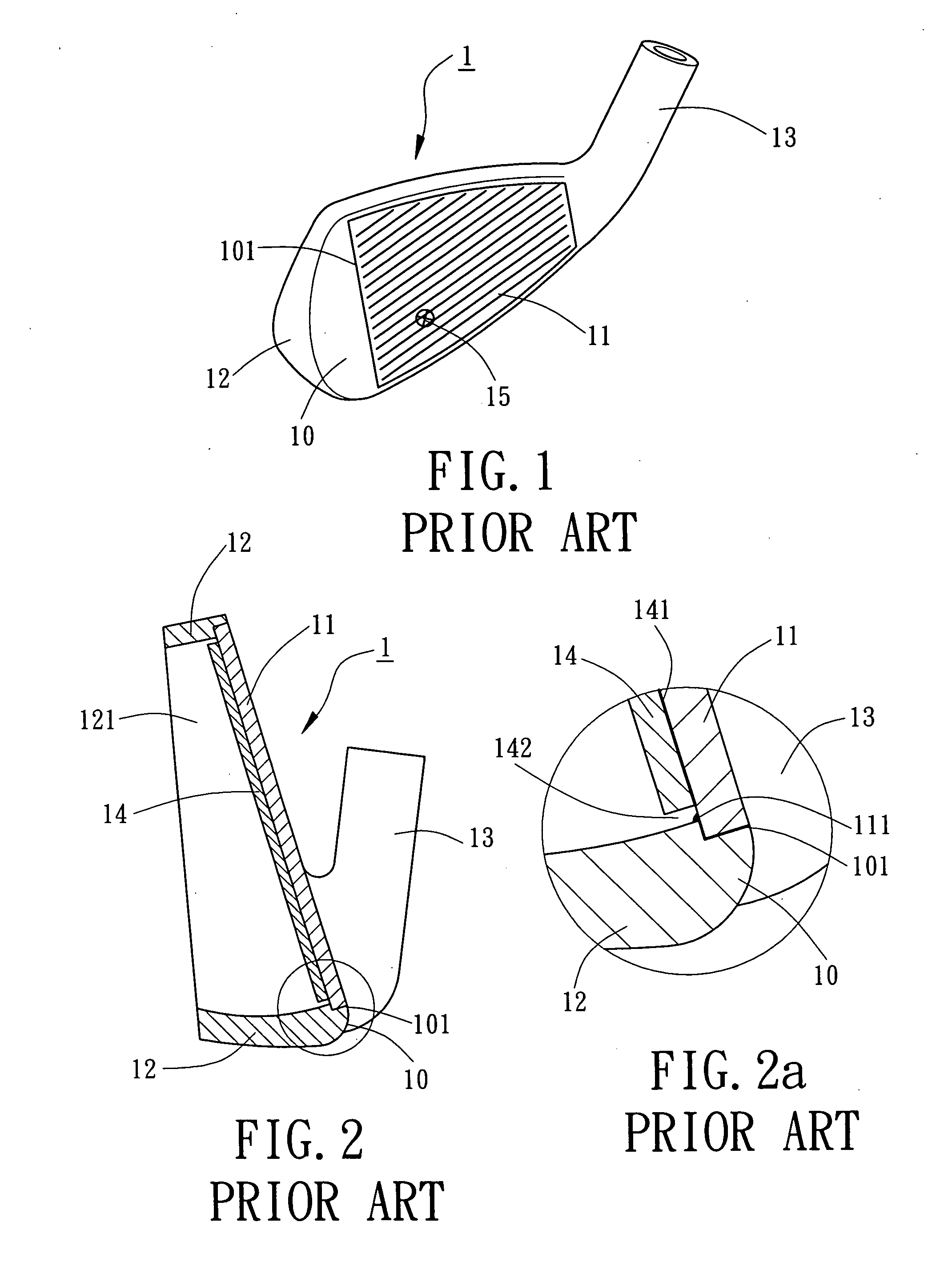
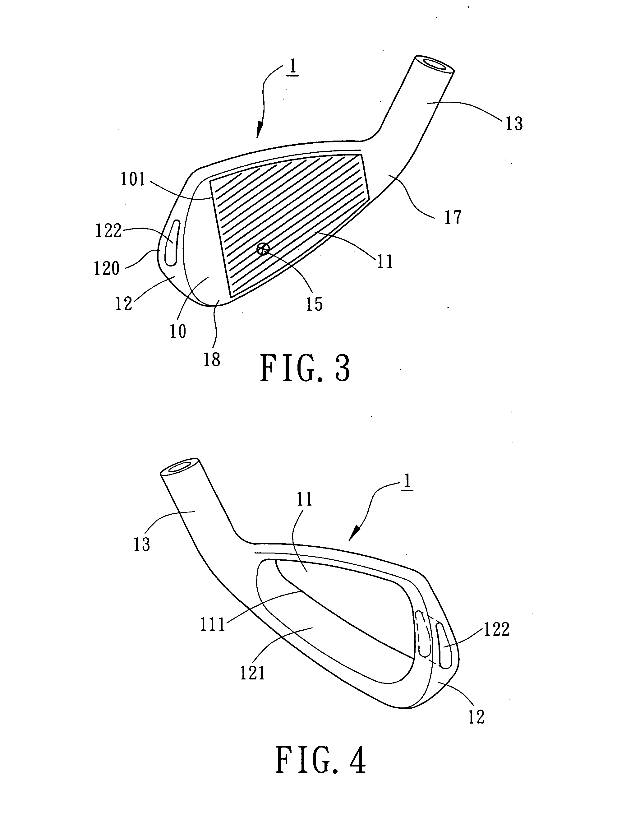
[0030] Referring to FIGS. 3 and 4, a golf club head 1 in accordance with the present invention includes a golf club head body 10 having an engaging portion 101 on a front side thereof. A striking plate 11 is mounted to the engaging portion 101 of the front side of the golf club head body 10 for striking a golf ball. The striking plate 11 can be mounted to the engaging portion 101 of the golf club head body 10 by insertion, pressing, brazing, welding, and screwing. Alternatively, the striking plate 11 can be directly and integrally formed on the golf club head body 10.
[0031] A perimeter wall 12 extends rearward along a perimeter 18 of the golf club head body 10 and defines an opening 121 in a back of the golf club head body 10. A hosel 13 is formed on a side of the golf club head body 10 and engaged with a shaft (not shown). A hole 122 is defined in a toe 120 of the perimeter wall 12 to reduce the weight of the upper part of the perimeter wall 12 and the weight of the toe 120, thereb...
second embodiment
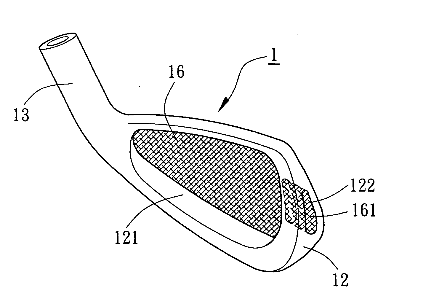
[0032]FIGS. 5 through 7a illustrate the golf club head in accordance with the present invention. In this embodiment, a reinforcing layer 16 is formed on a back of the striking plate 11 to improve the structural strength of the striking plate 11 and to support the string plate 11. The reinforcing layer 16 is a layer of light and reinforced material directly engaged on the back of the striking plate 11 via the hole 122 or the opening 121. A reinforcing block 161 extends from the reinforcing layer 16 and fills the hole 122 to provide an aesthetic appearance for the golf club head 1. The reinforcing block 161 is integrally formed with the reinforcing layer 16 as a single member. Preferably, the reinforcing layer 16 and the reinforcing block 161 are made by means of heat pressing or injection molding. The light material is preferably selected from a group consisting of carbon fibers, resins (such as epoxy resins), high molecular polymer materials, rubber, light alloys (such as titanium a...
third embodiment
[0034]FIG. 8 illustrates the golf club head in accordance with the present invention. In this embodiment, the hole 122 is a blind hole that has an opening in an outer face (not labeled) of the perimeter wall 122. By means of adjusting the specification and type of the hole 122 in the golf club head 1 (e.g., increasing the size of the hole 122), the weight of the upper part and the weight of the toe of the golf club head 1 are varied. This allows flexible adjustment of the position of the center of gravity 15. Thus, provision of the hole 122 increases the inertial moment of the golf club head and improves the striking effect of the golf club head 1 (i.e., increases the flying distance of the golf ball stricken by the golf club head 1). Further, the reinforcing block 161 that fills the hole 122 can be formed by means of heat pressing or injection molding, providing an aesthetic appearance for the golf club head 1.
[0035]FIG. 9 illustrates a fourth embodiment of the golf club head in ac...
PUM
 Abstract
Description
Claims
Application Information