Cooling system for power storage mechanism, cooling method of the same, and vehicle

a technology of power storage mechanism and cooling system, which is applied in refrigeration machines, propulsion using engine-driven generators, refrigeration components, etc., can solve the problems of reducing the space of the cabin compartment or the luggage compartment, requiring a space for the exhaust duct, and deteriorating the cooling performan

Inactive Publication Date: 2005-06-30
TOYOTA JIDOSHA KK
View PDF3 Cites 60 Cited by
  • Summary
  • Abstract
  • Description
  • Claims
  • Application Information

AI Technical Summary

Benefits of technology

[0009] It is an object of the invention to provide a cooling system for a power storage mechanism, cooling method of th

Problems solved by technology

The aforementioned system, however, requires a space for the exhaust duct.
This may reduce the space of the cabin compartment or the luggage compartment.
If the size of the exhaust duct is reduced, that is

Method used


Image

  • Cooling system for power storage mechanism, cooling method of the same, and vehicle
  • Cooling system for power storage mechanism, cooling method of the same, and vehicle
  • Cooling system for power storage mechanism, cooling method of the same, and vehicle

Examples


first embodiment

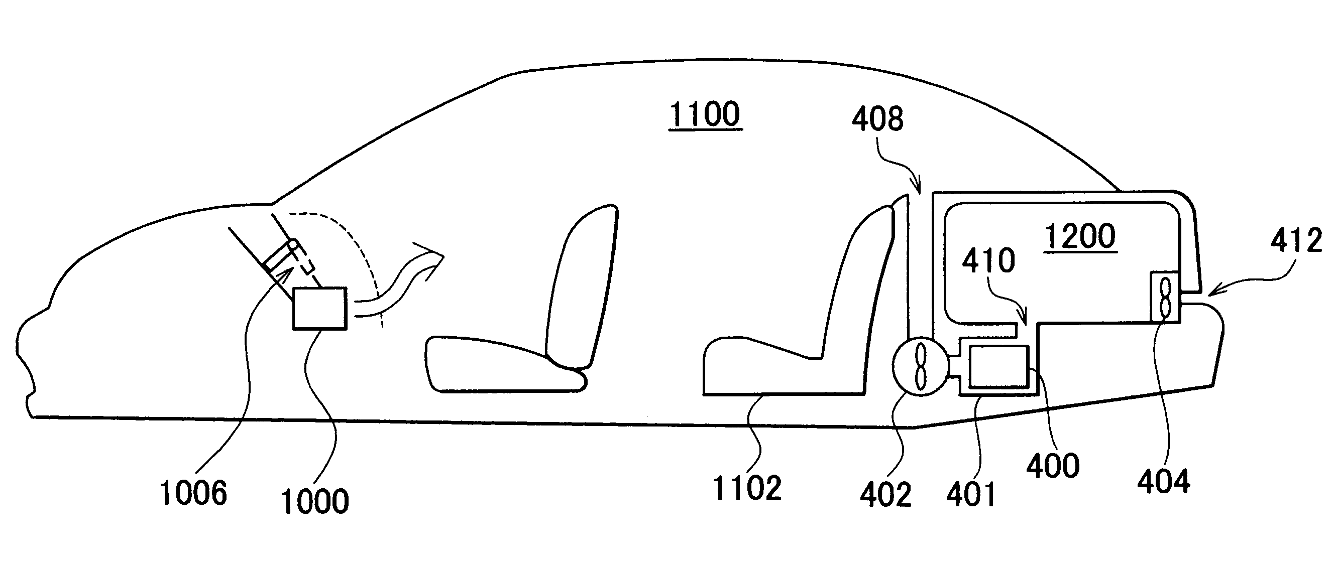
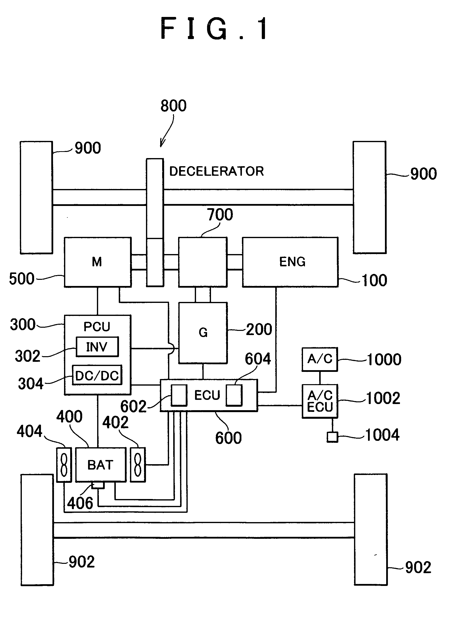
[0031] Referring to FIG. 1, a vehicle equipped with a cooling system of a first embodiment according to the invention will be described. The vehicle is equipped with an engine 100, a generator 200, a PCU (Power Control Unit) 300, a battery 400, a motor 500, a hybrid ECU (Electronic Control Unit) 600 connected to all the aforementioned units, an air conditioning (hereinafter referred to as an A / C) unit 1000, and an A / C ECU 1002 connected to the A / C unit 1000.

[0032] The vehicle in this embodiment is a hybrid vehicle equipped with the engine 100. However, the vehicle according to the invention is not limited to the hybrid vehicle equipped with the engine 100. The invention may be applied to a hybrid vehicle equipped with a fuel cell (fuel cell vehicle) instead of the engine 100 or an electric vehicle equipped with a battery 400 only.

[0033] The power generated by the engine 100 is divided into two channels by a power transfer 700, one channel for driving wheels 900 via a decelerator 8...

second embodiment

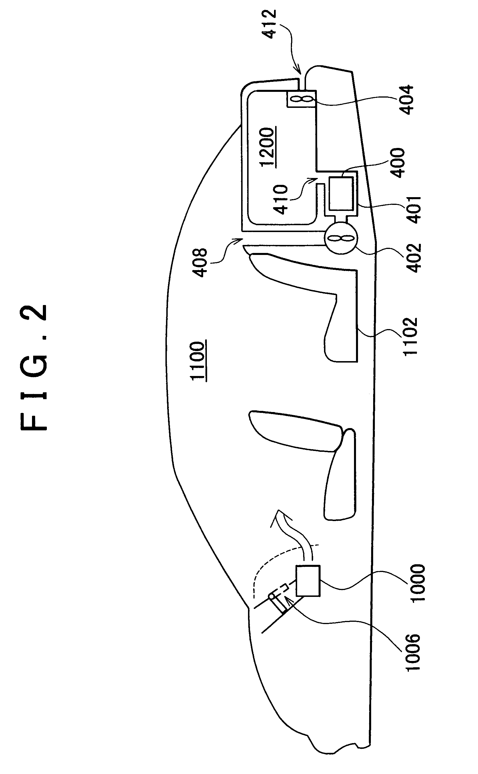
[0058] A second embodiment of the invention will be described referring to FIG. 6. In the first embodiment, the cooling system is employed in the vehicle of sedan type including two sections, that is, cabin compartment and a luggage compartment. In this embodiment, the cooling system is employed in the vehicle of wagon (hatch-back) type in which the cabin compartment and the luggage compartment are not sectioned. Other characteristics such as hardware and control routine are the same as those in the first embodiment. The explanation of those characteristics in detail, thus will not be repeatedly described.

[0059] Referring to FIG. 6, the vehicle includes a cabin compartment 1110 and a luggage compartment 1210 that are connected with each other. The cabin compartment 1110 is parted from the luggage compartment 1210 with a tonneau cover 1212. The element that parts between the cabin compartment 1110 and the luggage compartment 1210 is not limited to the tonneau cover 1212, but may be ...

third embodiment

[0060] A third embodiment of the invention will be described referring to FIG. 7. In the first embodiment, the cooling system is employed in the vehicle of sedan type including two sections, that is, a cabin compartment and a luggage compartment. In this embodiment, the cooling system is employed in the vehicle of mini van type in which the cabin compartment and the luggage compartment are not sectioned. Other characteristics such as hardware and control routine are the same as those in the first embodiment. The explanation of those characteristics in detail, thus will not be repeatedly described.

[0061] As shown in FIG. 7, the vehicle includes a cabin compartment 1120 and a third seat 1122 provided at a rear of the compartment 1120. An inlet 416 is formed at a position downward of the third seat 1122. An outlet 410 is formed at a position to the rear of the third seat 1122. The cooling air at the temperature increased by the heat transfer with the battery 400 is released rearward o...


PUM


Abstract

A battery pack is communicated with a luggage compartment via an outlet such that cooling air that has been heat transferred with a battery is released into the luggage compartment. A ventilation hole is formed in a rear portion of the luggage compartment. An inlet is opened toward the outside of the vehicle. An exhaust fan that discharges the cooling air at the temperature increased through heat transfer with the battery in the battery pack is provided to the front of the ventilation hole.

Description

INCORPORATION BY REFERENCE [0001] The disclosure of Japanese Patent Application No. 2003-433305 filed on Dec. 26, 2003, including the specification, drawings and abstract are incorporated herein by reference in its entirety. BACKGROUND OF THE INVENTION [0002] 1. Field of Invention [0003] The invention relates to a cooling system for a power storage mechanism, and more particularly to a cooling system for a power storage mechanism for discharging air that has been heat transferred with the power storage mechanism therefrom into the interior of a vehicle. [0004] 2. Description of Related Art [0005] Hybrid vehicles, fuel cell vehicles, electric vehicles and the like, driven by the driving force of the motor have been well known. The vehicle of the above type is equipped with a battery, capacitor and the like so as to store electricity supplied to the motor. As the battery and the capacitor generate heat upon charging or discharging of electricity, they need to be cooled. [0006] JP-A-10...

Claims


Application Information

Patent Timeline
IPC IPC(8): B60H1/00B60H1/32B60K6/28B60K1/04B60K6/445B60K6/54B60K11/06B60L11/18B60L50/16F25B39/04F25D17/00H01M10/60H01M10/613H01M10/625H01M10/633H01M10/643H01M10/651H01M10/6563H01M10/663
CPCB60H1/00278B60H2001/003B60H1/00385B60L1/003B60L7/14B60L2210/10B60L2210/40B60L2240/34B60L2240/36B60L2240/545Y02T90/16B60L50/40B60L50/61B60L50/16B60L58/12B60L58/21B60L58/26B60L50/66Y02T10/62Y02T10/70Y02T10/72Y02T10/7072
Inventor KIKUCHI, YOSHIAKI
Owner TOYOTA JIDOSHA KK
Why Eureka
Try Eureka