This helps you quickly interpret patents by identifying the three key elements:
Problems solved by technology
Method used
Benefits of technology
Benefits of technology
[0023] It is another object of the present invention to provide methods which enables an enhanced resolution to be obtained for dot-addressed displays.
[0024] It is another objective of the present invention to form pixel groups of quad pixels of 4 dots arranged in a matrix of 2×2 to represent the three primary colors Red, Green and Blue wherein same color dot can not be adjacent in the X and Y axis and wherein the area of the first color dot is the same as that of the third color dot, the area of two second color dots is the same as that of the third color dot. A weighted dot rendering method is applied in this display to create a perceived high resolution display.
[0025] It is another objective of the present invention to form pixels group of quad pixels of 4 dots arranged in a matrix of 2×2 to represent the three primary colors Red, Green, Blue and a forth color White wherein same color dot can not be adjacent in the X and Y axis. A weighted dot rendering method is applied in this display to create a perceived high resolution display.
Problems solved by technology
One drawback of this kind of display is that the number of pixels is limited by the fixed grid, which limits the resolution and the picture sharpness as well.
The fineness of the grid itself is limited by manufacturing technology, however, because the cathoderay tubes that are used for the displays comprise so-called shadow masks having holes therein which cannot be reduced to whatever size unless one puts up with considerable expenditures.
The drawback is that it still applies rigid pixel addressing method which limits the display further to improve its both horizontal and vertical resolution.
Likewise, in LCD displays, the integration of a great number of thin film transistors (TFT) is extremely expensive and very prone to produce major amounts of rejects.
In Plasma (PDP) or in FED displays, the technical and economical manufactured size of a RGB pixel is physically limited by the mass production technology itself and further reduction of the RGB pixel size for higher resolution cannot be achieved without huge manufacturing equipment cost and over proportional scraps which are economically not viable.
In LED displays, the placement of the LEDs is complicated and expensive as their space demand is predetermined by their shape.
Method used
Image
Click on the blue label to locate the original text in one second.
Reading with bidirectional positioning of images and text.
Examples
first embodiment
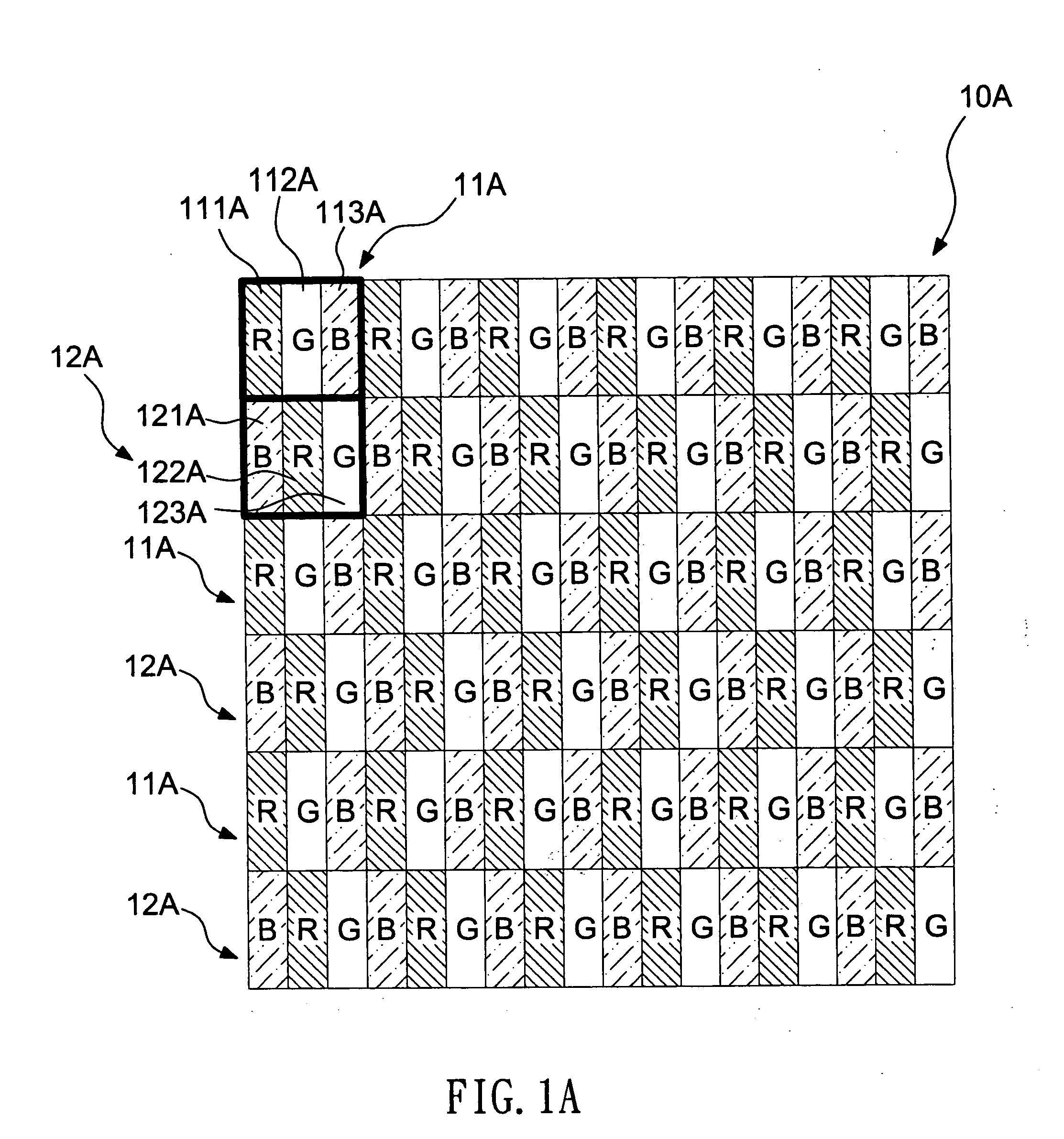
[0058] Referring to FIG. 1A, according to the invention, a display 10A comprises a plurality of first pixel groups 11A and a plurality of second pixel groups 12A. Each first pixel group 11A comprises a plurality of dots arranged in a matrix form, and each first pixel group 11A has at least one first color dot, at least one second color dot and at least one third color dot, for example, each first pixel group 11A comprises a red dot 111A, a green dot 112A and a blue dot 113A in sequence arranged in a 3×1 matrix.
[0059] Each second pixel group 12A comprises a plurality of dots arranged in a matrix, and each second pixel group 12A has at least one first color dot, at least one second color dot and at least one third color dot, for example, each second pixel group 12A comprises a blue dot 121A, a red dot 122A and a green dot 123A in sequence arranged in a 3×1 matrix. The first pixel groups and the second pixel groups arranged in a matrix manner to form the display so that the same color ...
third embodiment
[0074] Referring to FIG. 3A, according to the invention, a display 30A comprises a plurality of first pixel groups 11A, a plurality of second pixel groups 12A and a plurality of third pixel groups 13A. Each third pixel group 13A comprises a green dot 131A, a blue dot 132A and a red dot 133A in sequence arranged in a 3×1 matrix. The first pixel groups 11A, the second pixel groups 12A and the third pixel groups 13A are disposed in sequence along the Y-axis direction to form the display 30A. That is, the first pixel groups 11A are disposed in first row of the display 30A, the second pixel groups 12A are disposed in the second row of the display 30A, and the third pixel groups are disposed in the third row of the display 30A, in sequence. The first pixel groups 11A, the second pixel groups 12A and the third pixel groups 13A are stripe shape.
[0075] According to FIG. 3A-1, the selected dot (B) and two neighboring dots form an overlapping full color dynamics pixel group, and there are six ...
fourth embodiment
[0077] Referring to FIG. 4A, according to the invention, a display 40A comprises a plurality of first pixel groups 11A, a plurality of second pixel groups 12A and a plurality of third pixel groups 13A. The first pixel groups 11A, the third pixel groups 13A and the second pixel groups 12A are disposed in sequence along the Y-axis direction to form the display 40A. That is, the first pixel groups 11A are disposed in first row of the display 40A, the third pixel groups are disposed in the second row of the display 40A, and the second pixel groups 12A are disposed in the third row of the display 40A, in sequence. The first pixel groups 11A, the second pixel groups 12A and the third pixel groups 13A are stripe shape.
[0078] According to FIG. 4A-1, the selected dot (B) and two neighboring dots form an overlapping full color dynamics pixel group, and there are six overlapping full color dynamics pixel groups shown in FIG. 4A-1. A first overlapping full color dynamics pixel group comprises t...
PUM
Abstract
The invention relates to a display and a weighted dot rendering method. The display comprises a plurality of pixel groups, each pixel group comprising a plurality of dots arranged in a predetermined identical matrix form, each pixel group having at least one first color dot, at least one second color dot and at least one third color dot, the pixel groups arranged in a matrix manner so as to form the display, wherein each color dot has a plurality of sides adjacent to the other dots with different color, and each color dot represents a luminance and a chrominance of a corresponding full color pixel data by grouping with neighboring dots to form a plurality of overlapping full color dynamics pixel groups. In contrast with conventional RGB stripe arrangement which has high spatial frequency in X axe but 0 spatial frequency in Y axe, the arrangements of the invention have good spatial frequency in both axes, thus giving a higher visual perception of high resolution after performing weighted dot rendering methods of the invention where each dot in the displays represent the luminance and chrominance of each corresponding RGB pixel by forming with neighboring dots overlapping dynamic pixels.
Description
CROSS-REFERENCE TO RELATED APPLICATIONS [0001] This is a continuation-in-part of U.S. patent application Ser. No. 10 / 727,545, filed on Dec. 5, 2003; U.S. patent application Ser. No. 10 / 339,491, filed on Jan. 10, 2003; U.S. patent application Ser. No. 09 / 151,287, filed Sep. 11, 1998; and claims priority under 35 U.S.C. §119 and 37 C.F.R. §1.55(a) of German Application No. 197 41 132.0, filed Sep. 13, 1997.BACKGROUND OF THE INVENTION [0002] 1. Field of the Invention [0003] The invention relates to a display and a weighted dot rendering method. [0004] 2. Description of the Related Art [0005] In known display of the kind used in video, film and computer technology, so-called pixels are arranged along horizontally and / or vertically extending lines. The pixels generally consist of so-called dots representing the three basic colours red, green and blue. Dots are sources of luminous radiation the light of which is mixed to generate luminous mixed colours in a process referred to as additive...
Claims
Application Information
Patent Timeline
Application Date:The date an application was filed.
Publication Date:The date a patent or application was officially published.
First Publication Date:The earliest publication date of a patent with the same application number.
Issue Date:Publication date of the patent grant document.
PCT Entry Date:The Entry date of PCT National Phase.
Estimated Expiry Date:The statutory expiry date of a patent right according to the Patent Law, and it is the longest term of protection that the patent right can achieve without the termination of the patent right due to other reasons(Term extension factor has been taken into account ).
Invalid Date:Actual expiry date is based on effective date or publication date of legal transaction data of invalid patent.

